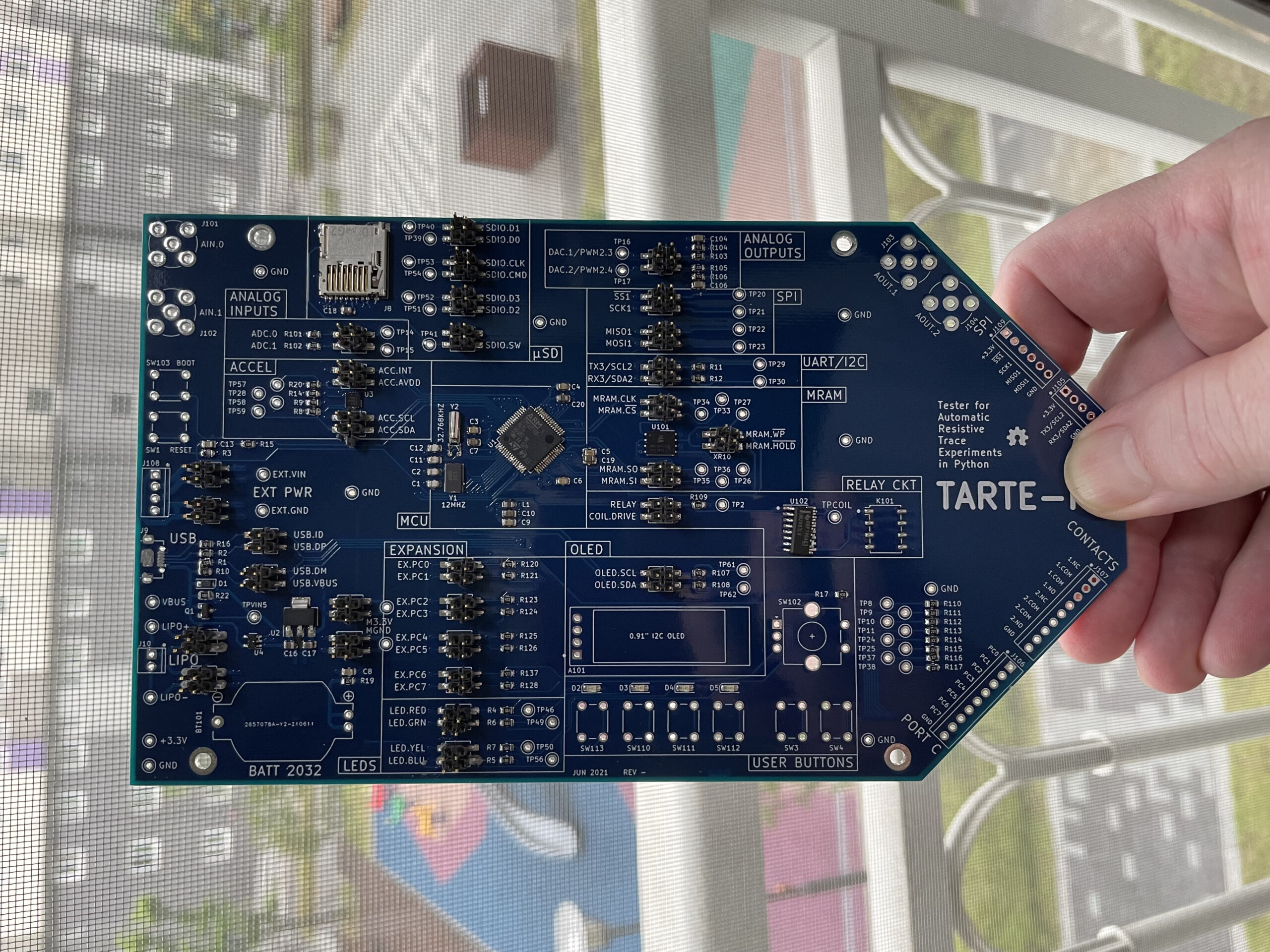
The Tarte-Py boards have arrived, they’ve been assembled, and they’ve tested. In fact, one of them is running a series of tests right now as I type this post. How did it go? In summary, it was one of the worse board bring-ups I’ve experienced in recent memory. The troubleshooting process was both frustrating and enjoyable at the same time. It was also quite time consuming, which accounts for the tardiness of this post. Fortunately, the problems were eventually solved and the boards are now working.
Problems Galore
The blank PCBs arrived as expected and had no observable issues. As I mentioned earlier, I decided to reflow these board myself in my lab — a first for The Stumbler. The process of using the stencil to apply solder paste went quite well. I hand placed parts on two boards instead of just one, reasoning that as a beginner I might fry a board on my first attempt. The first sign of trouble was when the solder paste began to dry out during parts placement. Despite this, oven reflow appeared to go well, although some parts near the edges weren’t soldered correctly. In hindsight, there were many more bad connections than I realized upon first inspection and touch-up. When you realize that every solder joint on the board can’t be trusted and could be compromised, it adds another level of complication (and anxiety) to the troubleshooting process.
I will be documenting more details in the build logs, but I’ll share two of the most memorable bugs here. In the ninth-inning of debugging the board, I could not make the USB DFU bootloader work no matter what I tried. I had two other STM32F405-based evaluation boards on hand to compare signals at boot-up, and everything seemed correct. Finally I realized that the crystal oscillator was the culprit.
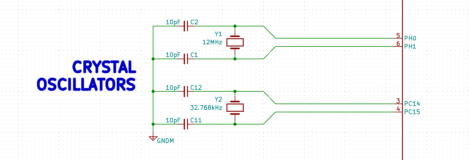
Adjusting the load capacitors on the crystal of an MCU oscillator is standard practice. You often have to tweak these capacitors to ensure the oscillator starts. My oscillator was running just fine. The culprit turned out to be its start-up time. All of the other bootloader interface ports of this MCU were working, but they rely on internal RC oscillator. But the DFU bootloader alone, because it uses USB, needs the accuracy of the crystal oscillator. Furthermore, it turns out that the oscillator must get up and running within a certain (undocumented) time limit. Once I figured that out, it was just a matter of changing the crystal shunt capacitors to make my oscillator stabilize more quickly.
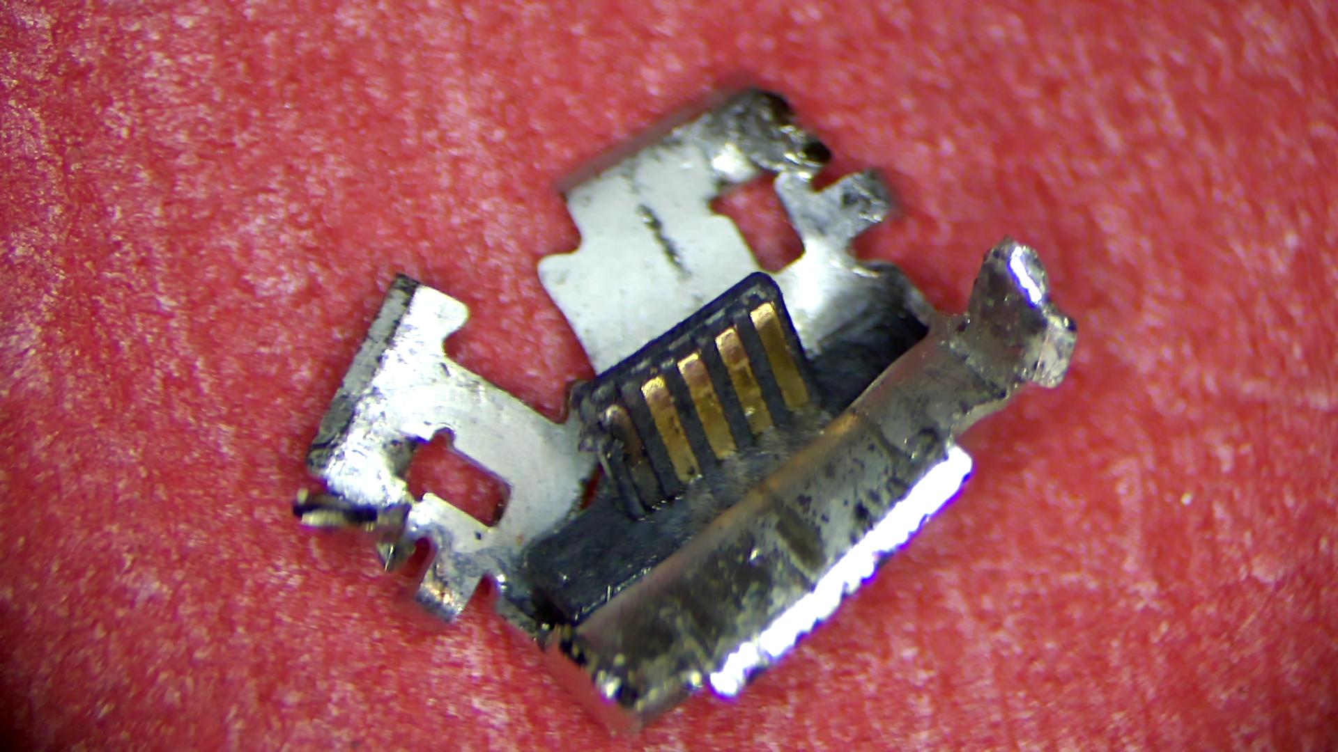
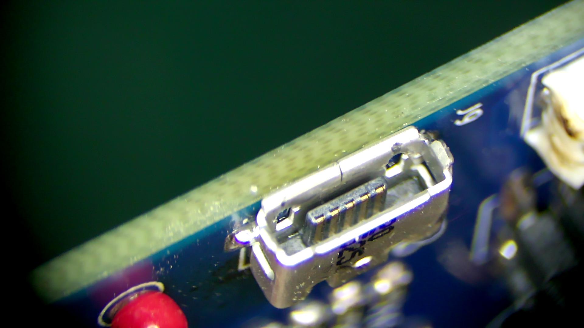
The final bug I solved was the micro USB connector. I suspected an issue with the connector, but I just couldn’t find the problem. I resoldered it a couple of times, and even built up the same USB circuit on the partially-completed second board and had no problems. It seemed that something wrong with this USB connector, but the connections seemed just fine when testing them statically. The ohm meter showed proper continuity on all pins, and the volt meter measured +5VDC as expected on the VCC pin. Things looked normal, except they weren’t. And then I happened to look at the mating portion of the connector for the Nth time, and I found it. Hidden from view and almost invisible to the naked eye, one of the pins was coated with a thin layer of black crud. This was no doubt caused by my overzealous resoldering attempts with the hot air gun. For reference, this is what a normal undamaged USB micro connector looks like on the inside — all the pins are shiny and sans crud.
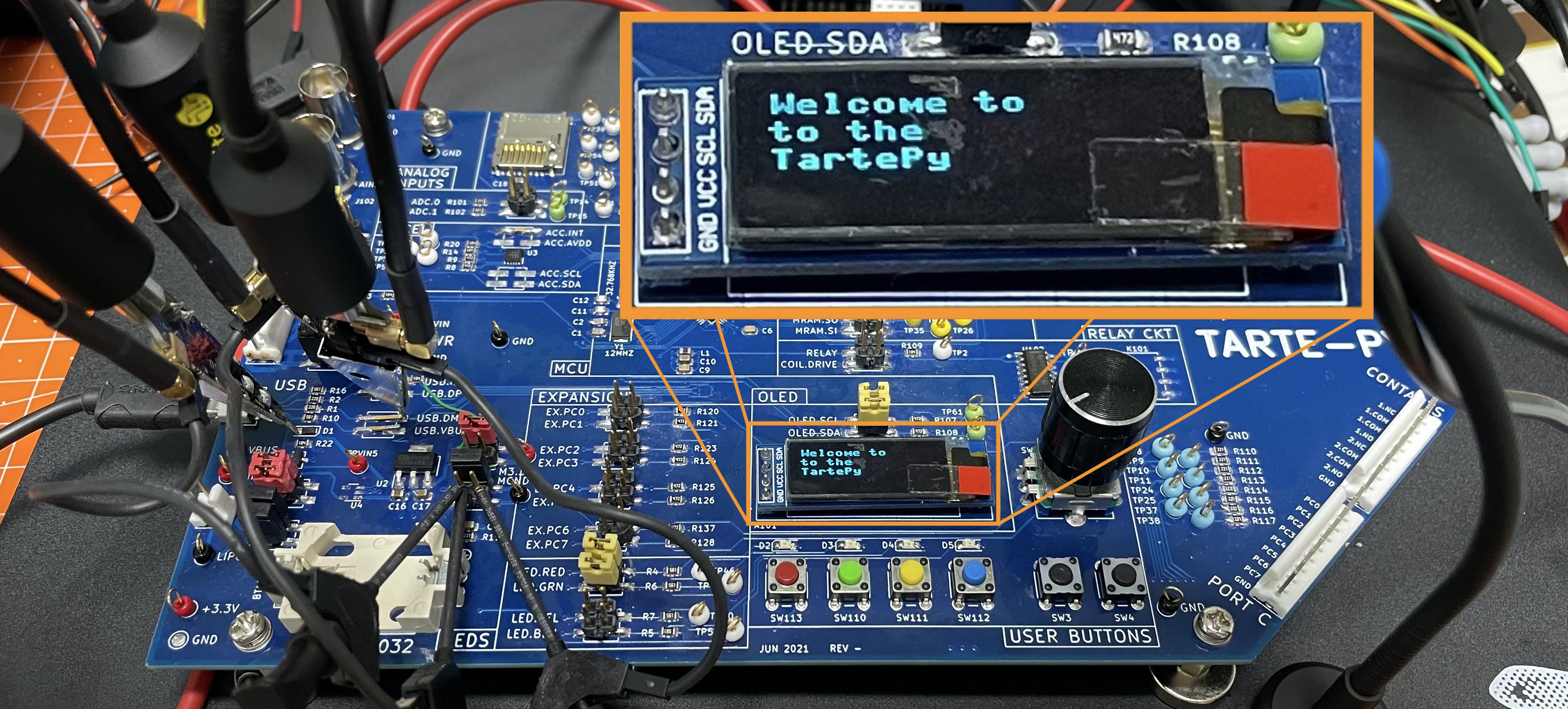
Once the connector was replaced, it only took a few minutes to install Micropython. I was so relieved to finally see this welcome message:
Calibrating the TraceR Modules
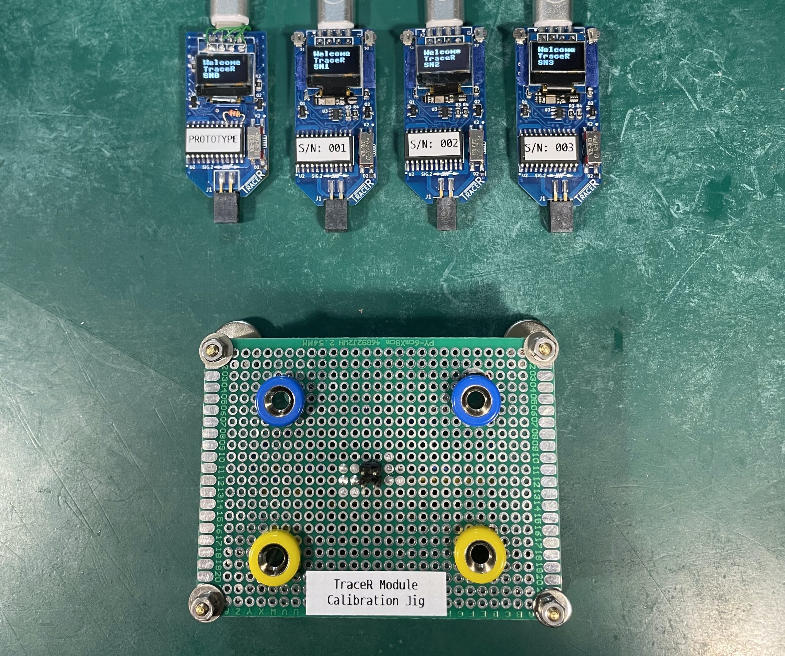
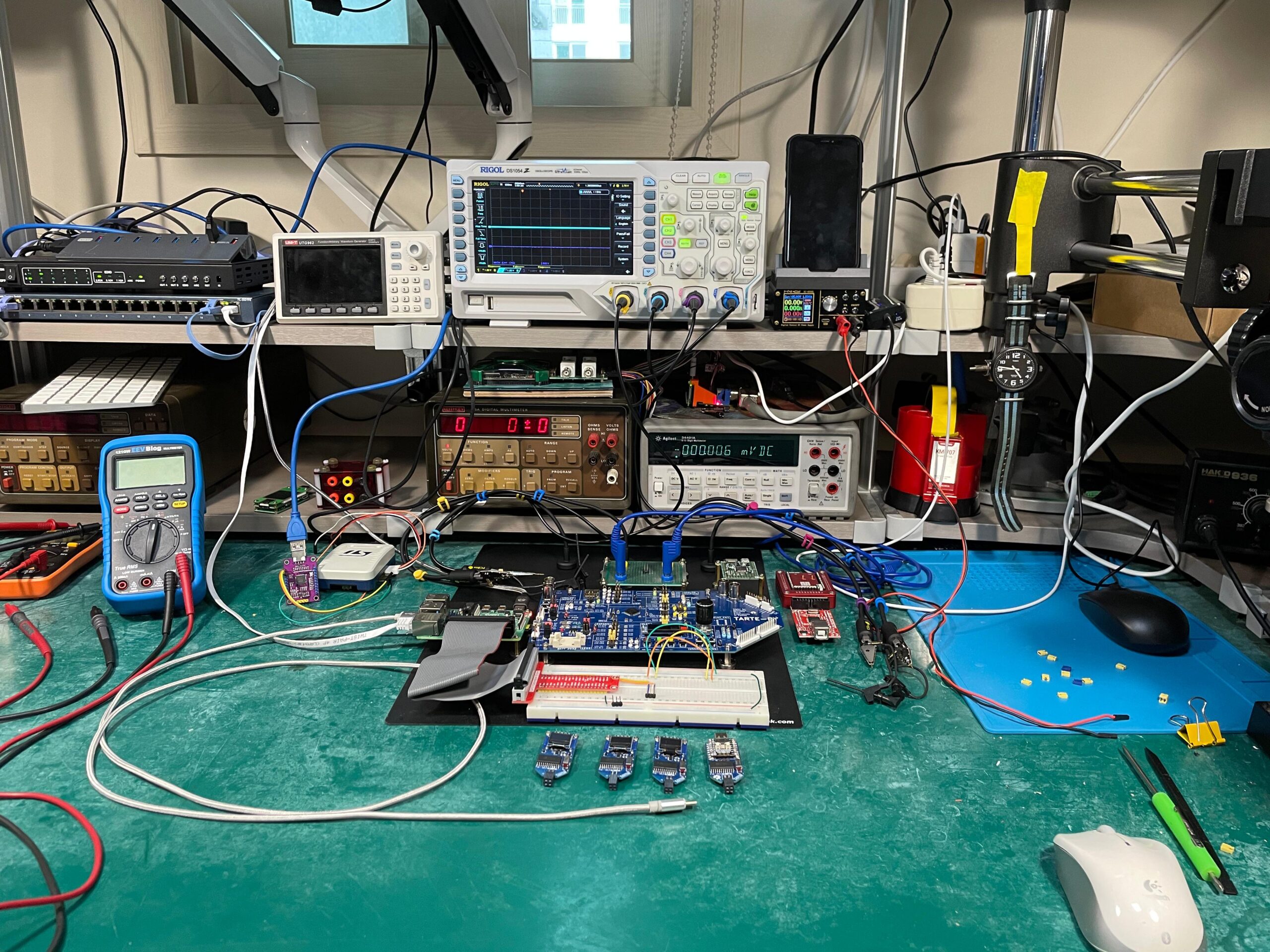
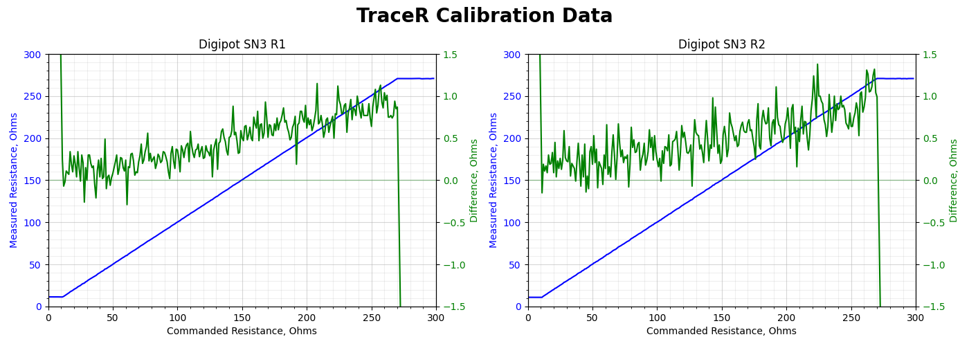
In parallel with the Tarte-Py circuit board debugging, I was also calibrating the TraceR modules. I made a simple test jig to easily measure the resistance by my Keithley 195A bench top digital multimeter. In a nutshell, this involved a Python script running on the test computer which would sweep through all wiper settings on the Digipot and record the actual measured resistance on the DMM. All the data so collected was then processed, inverted if you will, to generate a table of Digipot wiper registers for each integer ohmic value between the two wiper extremes — this varied a little with each Digipot, but was typically from 12 to 270 ohms.
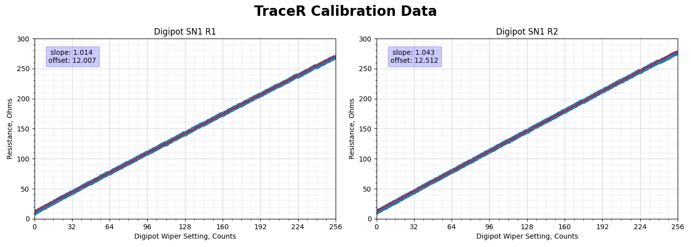
The plotted results are summarized below. And while it could probably be improved upon, the error is less than 0.15 ohms across the span of values. This seems more than adequate for this project. For some inexplicable reason, I have really enjoyed making and testing these tiny TraceR modules. I am continually thinking of ways to make them better and more flexible. Alas, I can’t think of any practical use for these widgets, even a super-duper improved version. If you have any ideas of how they could be useful outside of these lab experiments, let me know in the comments.
First Test
Ultimately one Tarte-Py was completely ready for testing, and second one is working but partially assembled (jumper pins and test points not installed). The Pyboard firmware was installed and it booted into Micropython right away. The first test I wanted to try is to see how increased trace resistance impacts asynchronous serial data communications. The test computer should send a packet of data to the Tarte-Py, which simply echoes it back. Repeated this many times and keep track of any errors as you increase the simulated trace resistance.
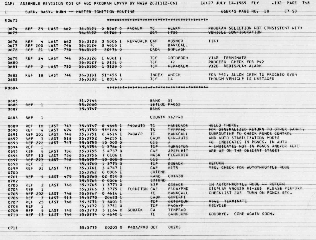
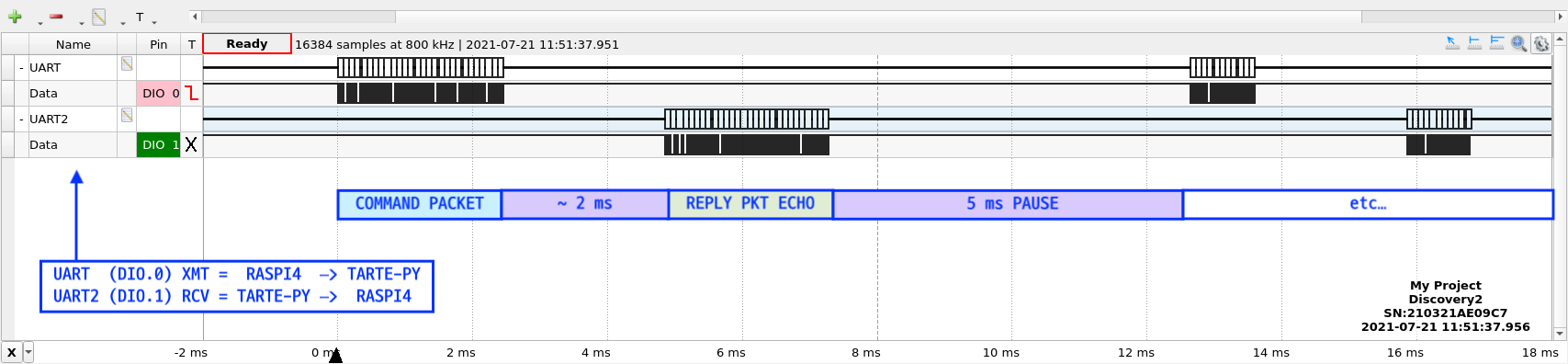
One could use random data for these test packets, but that’s boring. I decided a more interesting corpus would be the 65,614 lines of source code from Luminary 99, the control program used by the Apollo 11 Lunar Module back in 1969 (Note 1). Each line of source code is transmitted as a packet to which a 32-bit CRC is affixed. The echoed packet is checked and any errors are tabulated and logged. For any given simulated trace resistance, the test program cycles through the complete source code four times. I picked four cycles to give about an hour per run. This series of tests are done at 115200 baud with a pacing gap of five milliseconds between each transaction. The below screen capture from my Analog Discovery 2, operating in Logic Analyzer mode, shows this timing relationship for one of these packet transactions.
At this rate, one cycle through the source code takes about 15 minutes, and four cycles is about one hour. Six such runs were performed at 75 ohm steps as follows:
- Shunt (no TraceR, shorting jumpers used instead)
- R=11 (minimum TraceR resistance)
- R=75
- R=150
- R=225
- R=270 (maximum TraceR resistance)
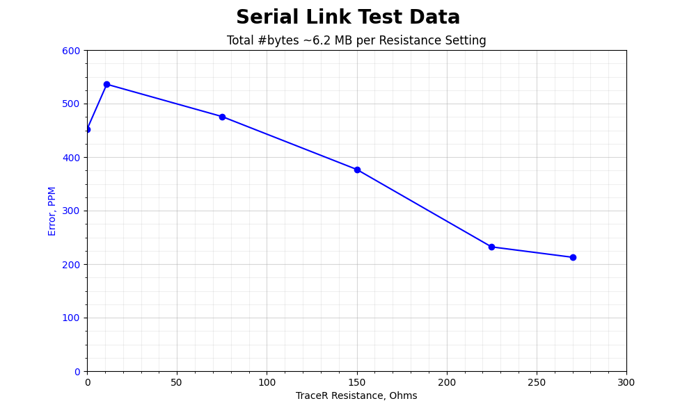
The following figure shows the tabulated results from these runs:
This is a Surprise
At this baud rate, and based on our previous estimates back in part two of this series, I wasn’t expecting the trace resistance to have much effect. But I’m doubly surprised at these results. First of all, these error rates seem too high for two microprocessors sitting on the same lab bench and communicating over tens of centimeters of wires. I wouldn’t expect to find any error in only one hour of data transmissions under these circumstances. I guess this is either the Raspberry Pi OS preempting my test program, or cross-talk / interference from the cabling or breadboard fixture. And while you might convince me that the TraceR module with its Digipots is the culprit, these errors are showing up with the TraceR is completely removed from the circuit and bypassed with shorting jumpers.
Secondly, the error decreases with increased trace resistance. This isn’t as crazy it seems at first glance, and may be the clue as to the unexpectedly high error rates. As we reviewed in part three, one thing increased trace resistance will do is to slow down the rise and fall times due to the input gate capacitance of ICs. If you are running at high speeds, this is an unwanted effect. The data speeds of this test are comparatively slow, but the edge transition times are the key factor. A square wave of only 1 Hz might be considered a “high speed” signal if the rise times are very fast — a 1PPS timing reference generated from the precise tracking oscillator inside a GPS receiver is one such example.
If there is unexpected noise or cross talk on the serial lines, increasing the trace resistance slows down the edge times, and this can reduce the unintentional radiated emissions and interference. In fact, this is a common technique used to slow down signal transitions in order to pass regulatory RF emissions tests. I/O pin transition times can even be programmed on some ICs for this exact reason. I will be exploring this issue further and will report my findings in a later post.
Speaking of Edge Times
Just out of curiosity, I did a quick-and-dirty test of edge times vs simulated trace resistance. Stepped the TraceR from one extreme to the other while data was being exchanged, and did an oscilloscope screen capture at each value along the way. Packing these into a short video clip, you can dynamically see the rise and fall times slowing down as the resistance is turned up.
What’s Next?
I will try to unravel the serial port error rate mystery next post, and also do some DC power trace tests. Also look for some more tests on edge times and higher frequency signal testing. If you have any particular tests you’d like me to explore, please post in the comments below.
Back to the Table of Contents
Forward to Part 6b: DC Performance Tests
Notes
- See the Luminary page from the Virtual AGC / Apollo Digital Archaeology site and Chris Garry’s GitHub repository.