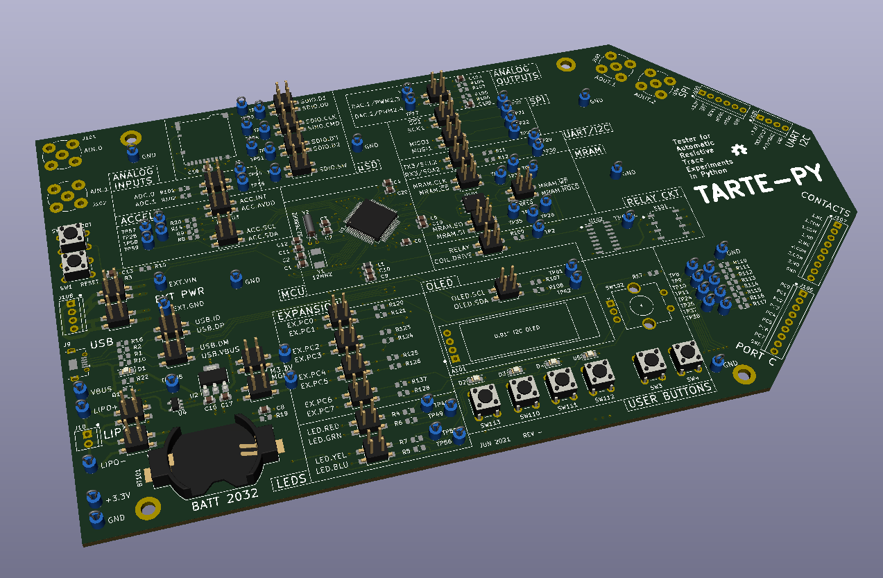
Today we will go over the hardware design of the MCU board, which I’ve named Tarte-Py: Tester for Automatic Resistive Trace Experiments in Python. The board follows closely in concept to the Pyboard as noted in Part 4, but with some slight circuit changes and big mechanical changes to better fit our application.
Pyboard Comparison, Features
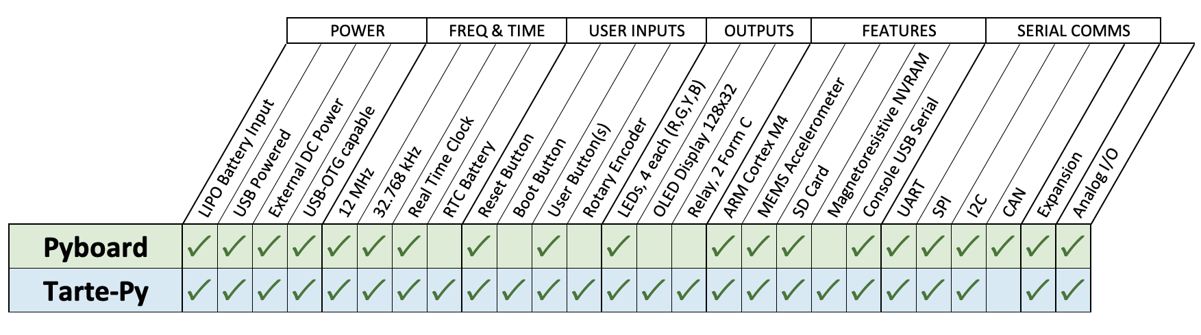
I’ve tried not to stray too far from the Pyboard design. All the basic features are present and connected in the same manner to the microprocessor. Above is a comparison chart of the basic features. Differences of note are summarized in the sections below.
USB On-The-Go Capability
The Pyboard has unpopulated circuitry to support powering a USB device. I thought we might have some future applications for this, so I populated the circuit on the Tarte-Py board.
Real-Time Clock Battery
The Pyboard has pins where you can connect a RTC backup battery. This keeps the date and time even when the board is not powered up. Since there is so much space on this board, that I went ahead and just put the battery itself (a CR2032 coin cell).
Boot Button
This MCU has a pin which controls whether the user code or a factory boot-loader is executed at power-up. I added a push button for this boot pin. Based on my experience, this can be helpful and there was plenty of room on the board.
User Buttons
I added several more user buttons in addition to the one present on the Pyboard. There are four new buttons corresponding to each of the four LED colors, plus two general purpose extra buttons. The push-action button of the new rotary encoder knob corresponds to the existing Pyboard user button.
OLED Display and Rotary Encoder
Just for fun, I added a rotary encoder dial input and an OLED display. These are inexpensive, require very few additional pins, and open up the possibility of a stand-alone menu driven system in the software.
Magnetoresistive NVRAM
This is another “just for fun” addition. I was recently watching this series on building a sub-$1000 cubesat, and found that magnetoresistive MRAM chips are readily available and not wildly expensive. As someone who has used a computer with real hand-threaded core memory, I just couldn’t resist the chance to play with this technology.
CAN Bus
I didn’t bring out the CAN bus to a connector, because I stole those MCU pins to interface with the MRAM and the OLED. Also, I don’t have any CAN widgets, and I didn’t see that we could learn anything new from CAN that we couldn’t learn from the other serial interfaces. That said, if we need to test the CAN bus interface later on, I can jumper those signals easily via test points.
Expansion
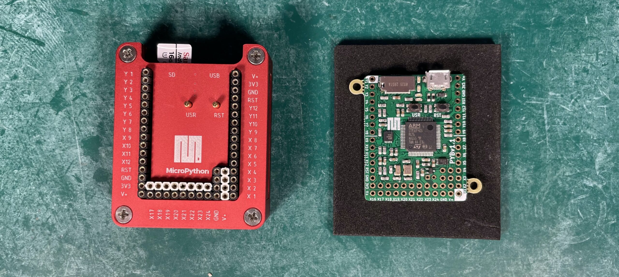
The Pyboard takes a clever approach implementing expansion modules. There are two groups of sixteen expansion pins are aligned along the edge of the board. These groups are labeled X and Y. Each group uses 8 pins from each side of the Pyboard. This way, a typical expansion module can be plugged into the Pyboard in either of two orientations, 180 degrees apart. For the Tarte-Py board, I decided a simple 8-bit port was sufficient for any expansions that we might need.
Analog I/O
The Pyboard has connections for all the ADC and DAC pins of the MCU. I felt that just two analog signals would be enough for this application. Accordingly, the Tarte-Py has two analog inputs, and two outputs. The outputs may be either a DAC signal or a PWM.
Pyboard Comparison, Mechanical
Damien George, the original author of Micropython and designer of the Pyboard, did a great job of cramming a lot of circuitry into a such a small package. My Tarte-Py version completely undoes all his hard work, exploding this compact 42 x 33 mm layout into a whopping 210 x 120 mm (an 18:1 increase). There was some method to my madness, however. Since I want to be able to insert the TraceR modules at many locations, I had to spread out the circuitry quite a bit. I also added copious test point for probing waveforms and voltages, and each test point takes up space as well. And since the board is already so big, why not put an OLED display, some buttons and a knob.
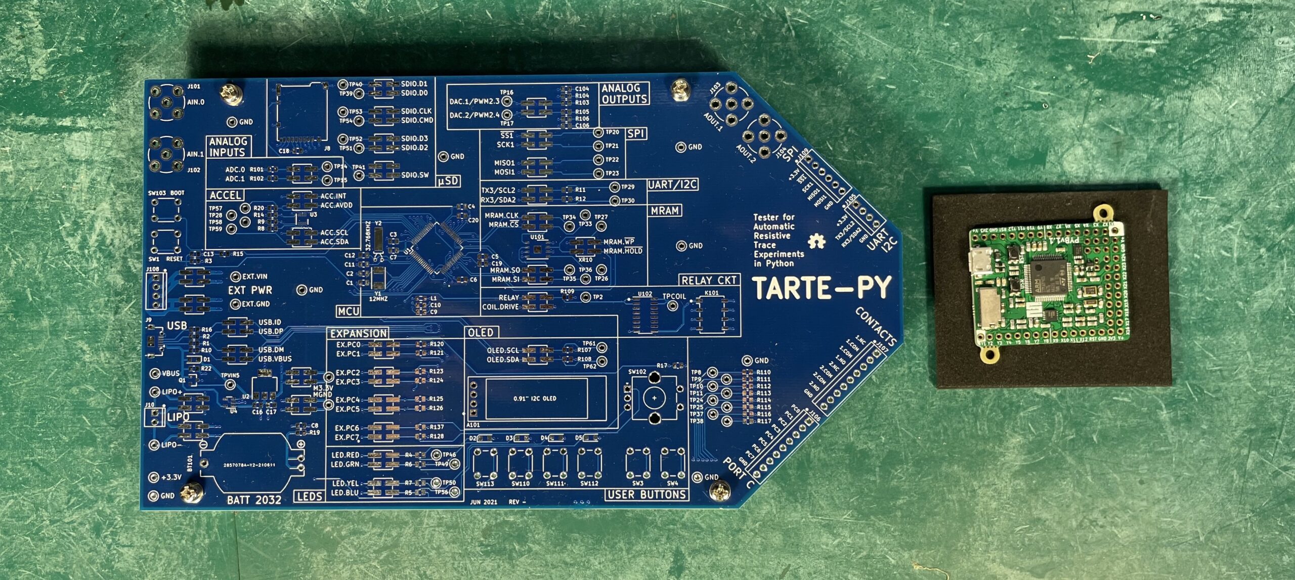
This is the real PCB, without parts, which just arrived a few days ago. What’s with the shape? Well, I really wanted to make it look like a big resistor symbol, but quickly realized that was too complicated. Instead, I took the shape of the TraceR module and scaled it up.
TraceR Module Socket Locations
I was liberal in placing TraceR sockets on almost every signal imaginable. These fall into a few categories.
- Normal low-current signals used for I/O
- Higher current relay / LED drive signals
- Power supply traces
Because the TraceR modules incorporate a pair of traces in their design, the sockets are arranged in pairs as well. The power traces put both variable resistors of the TraceR module in parallel to lower the resistance and increase the current carrying ability.
Why Are We Doing This Again?
You might reasonably wonder, why go to the effort of molding our project to mimic an existing project. Why not just make a unique board from scratch, with exactly those connections and devices needed and no more. The answer is two-fold. First of all, almost any MCU would be suitable for this trace resistance project — its requirements are very flexible. Since I could make a suitable board in a dozen different ways, why not use the Pyboard as a starting point? The second reason is that we’re not building upon just any open source project. Instead, we’re building upon Micropython designer’s reference board designed precisely for Micropython. Sure, I could make a custom designed board, tweak the Micropython parameters, and compile my own version of Micropython. But there is no reason to do this. With this selected approach I should be up and running in just minutes using the standard Pyboard build of Micropython (knock on wood).
Build Logs and Notes
Those of you who are just interested in the experiments and bored by these electronic and software design details can now breathe a collective sigh of relief. From now on, I will be putting my detailed design and reference notes into a build log of each relevant repository. These will be in, or linked to from, the readme.md file so they will be easy to find. To date, the repositories for the designs are as follows:
- TraceR Module
- Tarte-Py Module
- Test Control Computer
What’s Next?
Now comes the really fun and exciting part of this project — build the boards and begin testing. I’m going to be elbows-deep in solder paste and Python this week. If all goes as planned, the next article will show the assembly and initial bringing up of the Tarte-Py board. I plan to do the serial data test first, and see how much trace resistance the link can tolerate.
Next up: Tarte-Py assembly and test
Back to the Table of Contents

2 Responses
I am a designer of disruptive technology specializing in the dissipation of warm air in the home by printing conductive inks onto material that attaches to the backing cloth of curtains.
There are issues with hot spots building up this maybe the result of a design fault in the CAD.
Do you have any experience with printing directly onto material.
I am looking for a manufacturing partner in the US.
Thank you for contacting NovaCentrix. Great question!
For printing conductive inks onto fabrics, we generally recommend printing onto TPU, then applying that TPU to the fabric. The reason for this is a combination of ink performance and processing requirements, fabric origin, fabric type, fabric flexibility, weave and thread count. We do offer starter screen printing ink kits and screen printing ink on our webstore: https://store.novacentrix.com/category-s/1817.htm
While we do not have a specific recommendation for a manufacturing partner, we suggest you consider contacting a fabric screen printer in your area that may have experience in printing conductive inks, or they may refer you to a suitable partner.
Don’t hesitate to reach me at 512-565-4415.
With best regards,
Rick Larson
Sales Manager
NovaCentrix