Transient Analysis
In this post we will examine some transient response tests as a function of trace resistance. And I’ve found the solution of the less-than-perfect serial port errors. This is part 7 of the series on conductive inks, and will wrap up the experiments portion of this series. The next and final post will be a summary of lessons learned.
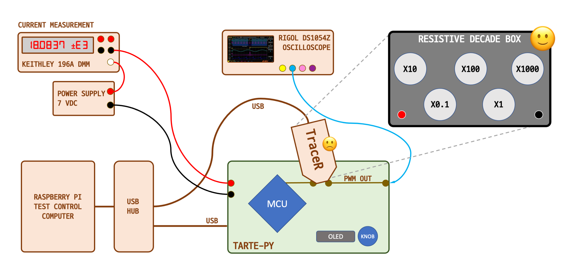
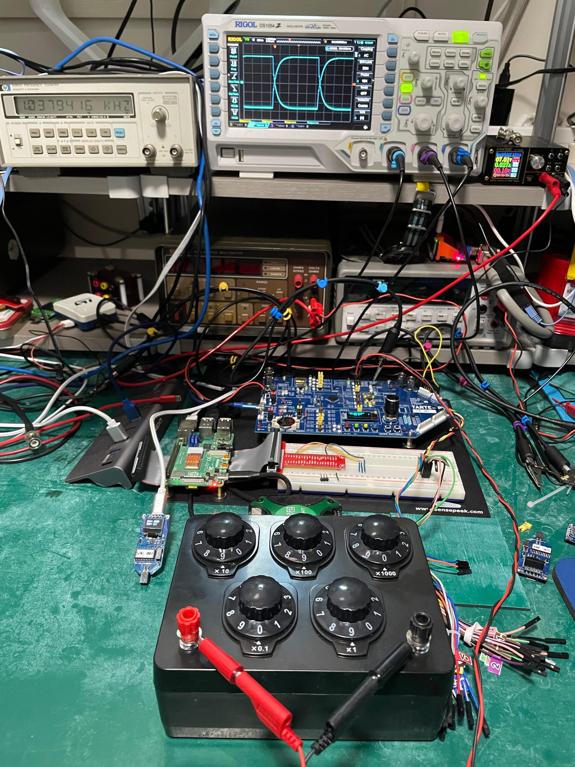
We got a taste of transient response at the end of part 6a, when I plotted transition times of the 115,200 baud serial experiment. This time, we will use the PWM output mode and just generate a high-speed (relatively speaking) square wave. Monitor this on the oscilloscope and capture the “eye-diagram” as we increase the simulated trace resistance. Sounds easy.
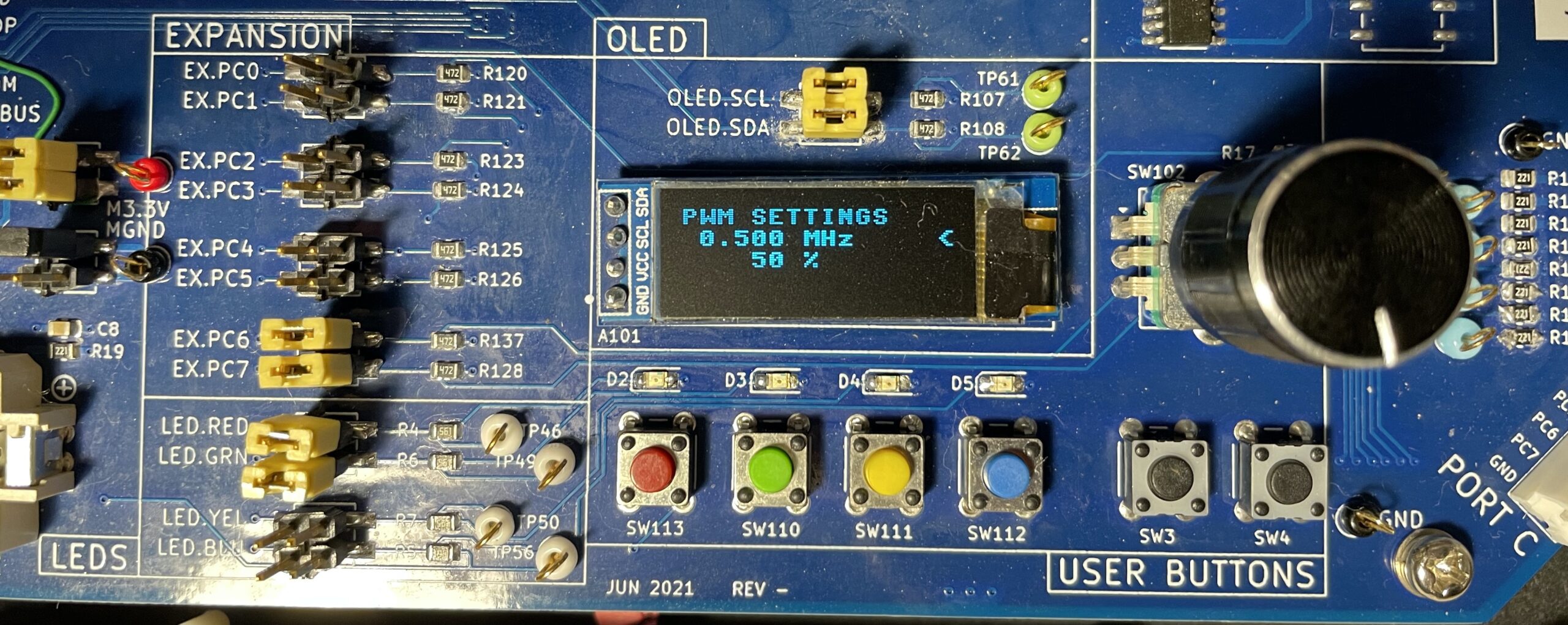
I wrote a short test program to configure the PWM output using the rotary dial and OLED screen (see note below). With this simple interface, you can set frequency of the pulses and the duty factor (which I left at 50% during these tests). The goal here is to use a signal that’s up in the several MHz rather than KHz range.
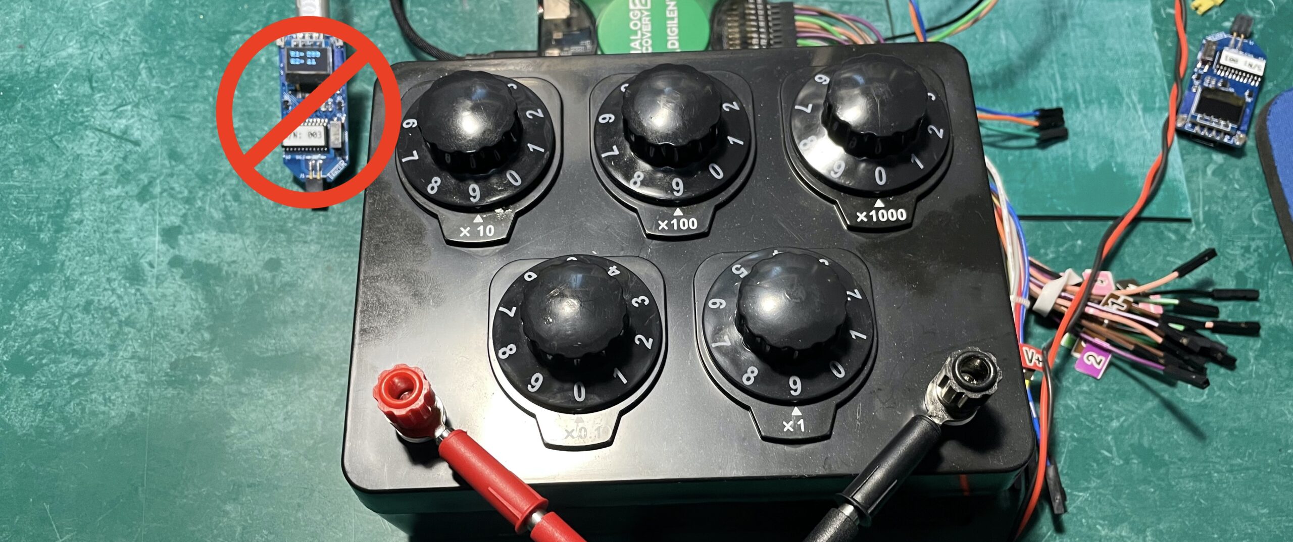
This is going to push the limits of my TraceR module, which as you may recall from part 5a, has a bandwidth limit of several MHz as well. And indeed, using the TraceR caused some weirdness in the signal. Digipots aren’t quite real resistors, and they have some voltage restrictions and are connected on one side to a running MCU. Rather than stopping the tests and designing a new TraceR from scratch, I opted to pull the decade resistance box off the shelf and use that instead. Since it’s controlled by hand using a bunch of rotary switches, that means this test won’t be automatically controlled.
Rapid Transitions and Overshoot
With no simulated trace resistance, the pulse transitions ring for a few nanoseconds before settling down. This is to be expected when you have rapid rise times driving a high impedance load. In fact, designers often put series resistors on such traces to slow down the transitions and reduce unintended RF emissions.
So next I began increasing the simulated trace resistance using the knobs on the decade resistor box. I went in ten ohm steps, grabbing an oscilloscope screen capture each time. With only 26 steps between 0 and 250, and the screen capture consisting of running a quick Python script, the process wasn’t too painful. Putting all 26 traces in a single figure was too messy, so I only show the data at 50 ohm steps in the figure below. As you can see, and as we expect, when the simulated trace resistance is increased, the rise times decrease and the ringing becomes damped.
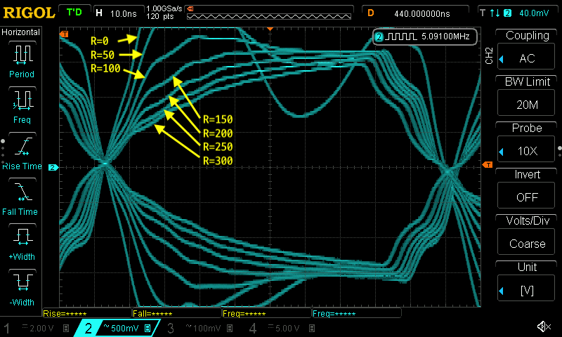
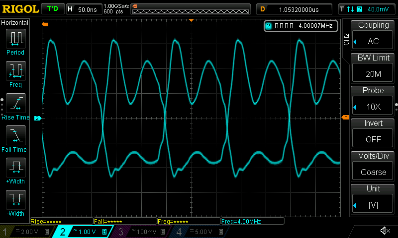
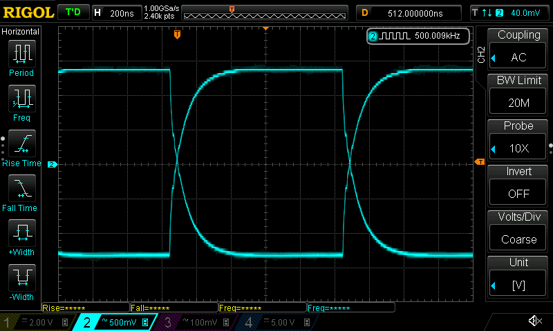
Looking at the 300 ohm eye diagram trace, it looks pretty bad. It is basically a saw tooth shape — the signal changes state before the voltage at the load has had a chance to stabilize. You probably wouldn’t want to operate your circuits in this regime. But to put things into perspective, let’s take a look at a 500 KHz signal. This is almost five times the frequency of our 115,200 baud serial link from before. Even if I crank up the trace resistance to 1000 ohms, when viewed from a 500 KHz square wave the slow rise time very likely won’t be a problem.
We can conclude from these tests that using conductive ink traces on such signals not only isn’t bad, in many circuits it is helpful. There are some exceptions which could prove challenging to solve. If your design relies on a precise pulse edge for accurate timing, for example, you can’t have the signal leisurely ambling its way up to Vdd. If you’re driving a signal into a low impedance input, like 1K, 120, or 50 ohms, having traces of a hundred or more ohms is probably going to be unacceptable. We will look at some mitigation strategies for conductive ink circuit designs in future posts, but the simplest advice for now is to just keep the lengths of such traces very short.
Serial Link Errors, Mystery Solved
At least, I’m calling it solved. Feel free to challenge me if you have any other ideas. After the follow-on tests I reported on last week, I formed a working hypothesis. As fast as computers are these days, we sometimes forget that the typical operating systems (Windows, Unix/Linux, macOS) are NOT real-time. The OS can, and does, interrupt your task from time to time to go handle bookkeeping jobs. These can take tens of milliseconds, or even more when hard disk operations are involved. The test control computer was a Raspberry Pi, which is running its own tailored version of the Debian Linux distribution (formerly called Raspbian, not just Raspberry Pi OS). Considering the Pi is a slower computer than most, it seemed reasonable to conclude that I was losing serial characters because the OS was off doing housekeeping and the serial receive buffer overflowed.
There are several ways to test this theory, but I took a quick and lazy approach. The first, and laziest, test was to run the test program on a faster computer. I used a Debian desktop computer running an Intel Core i5-7500 CPU at 3.4 GHz. This processor is almost 8x more powerful than the Pi (see note below). Those tests completed with no errors.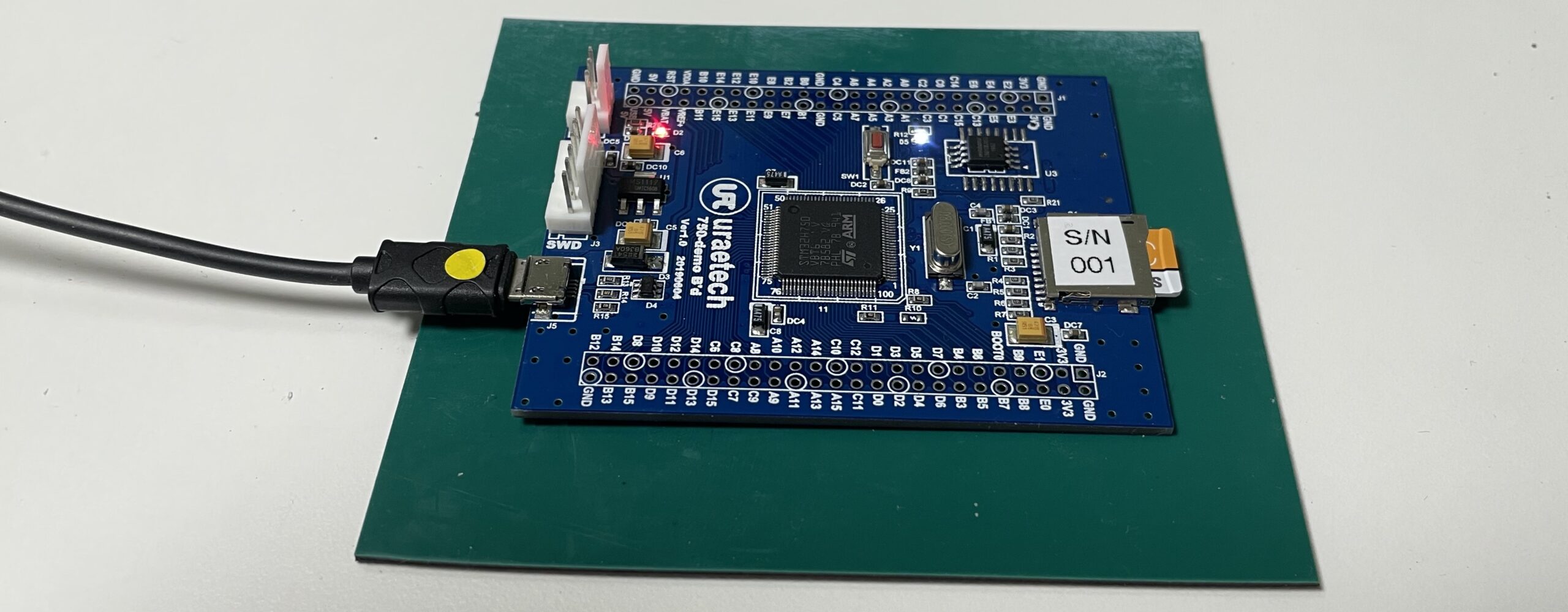
I wanted to do one more test, and selected a fast MCU: the STM32H750, a Cortex-M7F processor running at 480 MHz. I was able to procure a nifty demo board locally in South Korea, no small feat given the ongoing global chip shortages. I first ported Micropython to the board in short order, and then modified my Python testing script a little to run under Micropython (it lacks a few features of Python). Running the serial link tests from the Cortex-M7F also showed zero errors.
One could do more thorough debugging. For example, look at the serial port hardware registers and study the FIFO behavior as errors happen. Of course, one way to fix this is to avoid the situation entirely by implementing hardware handshaking. This can fix these kinds of problems, although I’ve seen UART designs that could still fail in certain circumstances despite the handshaking. But unless some other reason comes along to dig deeper into this, I’m calling this mystery solved.
Testing Wrap-up
With this post, we conclude the tests which I had initially planned for this series. A few more testing ideas have come to mind. But its difficult to determine which ones make sense to the conductive ink community. I’ve discovered some issues with the TraceR module, and will be pondering ways to improve on the design. Regardless, the test bench exists, and is available for further testing down the road. I also envision some new experiments associated with my next series of posts, to be revealed later.
What’s Next?
In the next and final post of the series, I will summarize all the lessons learned to-date. This will include a set of electronic design considerations to be aware of when designing your conductive ink printed circuit. Don’t forget to get in touch if you have any specific tests you’d like me to try out. With the test bench completed, it’s reasonably easy to perform new experiments.
Notes
- Keeping with the laziness trend, I searched around for a Python rotary encoder module I could quickly adapt in my code. I found this GitHub repository which was precisely what I needed. There was even an accompanying YouTube video by a bright girl whose entire family is into computer programming, hardware tinkering, and application development.
- This CPU comparison from PassMark shows a comparison between the Intel Core i5-7500 and the Broadcom BCM2711 processor.