Last article we looked into the ramifications of using conductive ink PCB traces from a static, DC perspective. Today I’m going to consider the implications from a dynamic point of view. Most of the signal interfaces we use in microcontroller designs today drive very high impedance loads. The impact of increasing the trace resistance connecting to the input gate is an increase in the rise time. Let’s take a look at that in more detail.
Rise Times Decrease
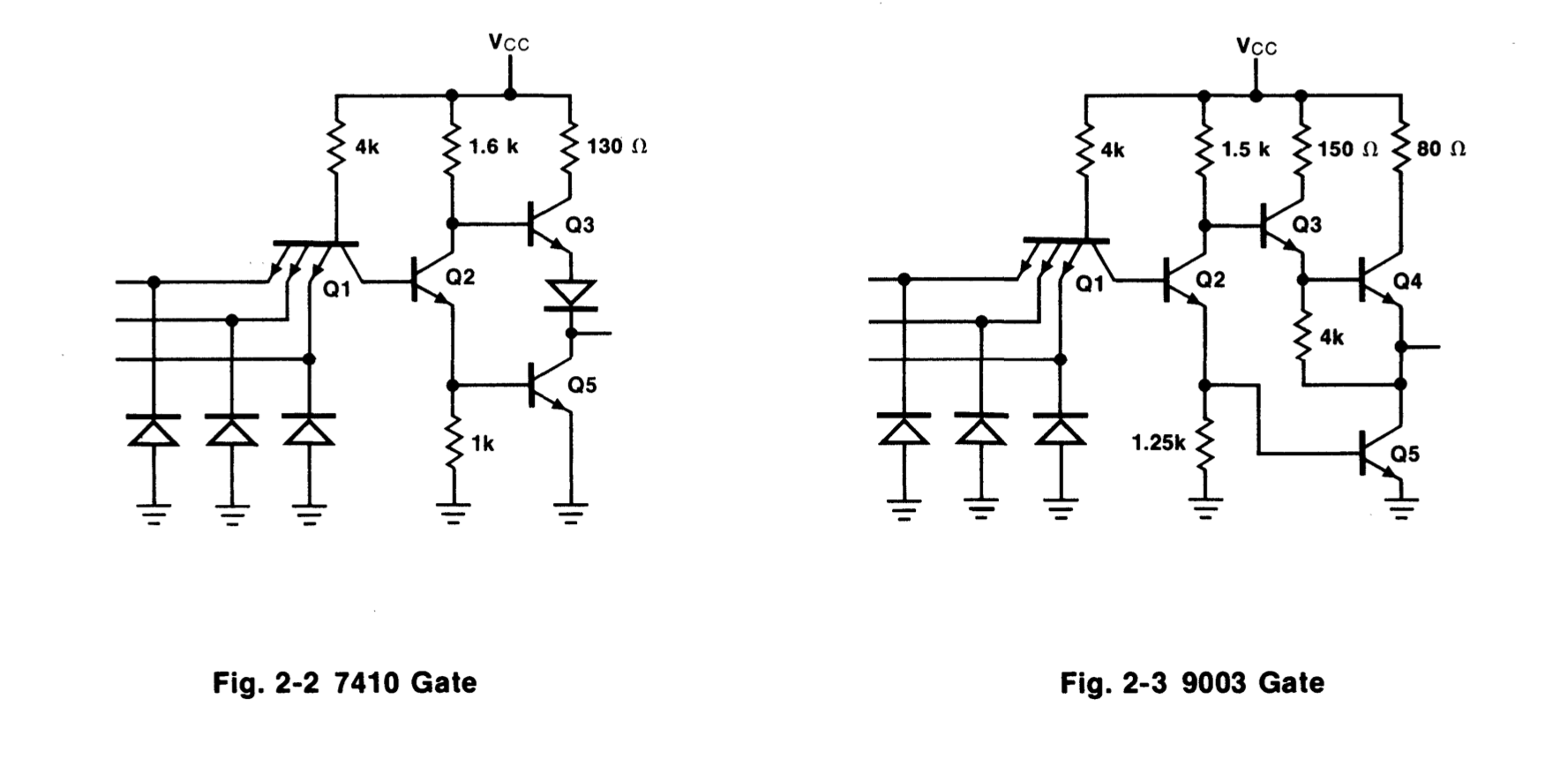
The main contribution to rise time degradation in modern MOS transistor-based inputs is going to be input gate capacitance. It would be nice to just plug in a SPICE model for the input circuitry, but it is rare to find manufacturers that provide that level of detail about their chips.
Spot-check a few data sheets and you’ll find a typical value is around 5 pF. We could just model and R-C circuit, but we can do a little better. It turns out that the common 2N7000 N-Channel MOSFET transistor has a 5 pF input gate capacitance, and the manufacturer provides SPICE models as well. I’ve used the 2N7000 from ON Semiconductor for this analysis.
Simulation
The circuit analysis tool SPICE (Simulation Program with Integrated Circuit Emphasis) was one of the first open-source computer programs. It was developed in the early 1970s by Laurence Nagel at the University of California, Berkeley and has spawned dozens of varieties over the years. If you’re curious, here is a short presentation that summarizes the history of SPICE given by Dr Nagel back in 2013. For these simulations, I am going to use Ngspice, a version included with the open-source KiCad electronic design automation (EDA) suite.
Traditionally, SPICE has been a text-based tool, reading inputs in a cryptic format and generating textual tables and even ASCII-art-like textual plots. Many newer projects have given GUI front-ends to SPICE, some better than others. Since the basic input to SPICE is a almost always expressed as a schematic, it’s not surprising that some EDA tools incorporate SPICE simulation, coupled closely with the schematic. KiCad began offering SPICE integration about three years ago, and while it’s not perfect, it is quite useful and is improving with each release.
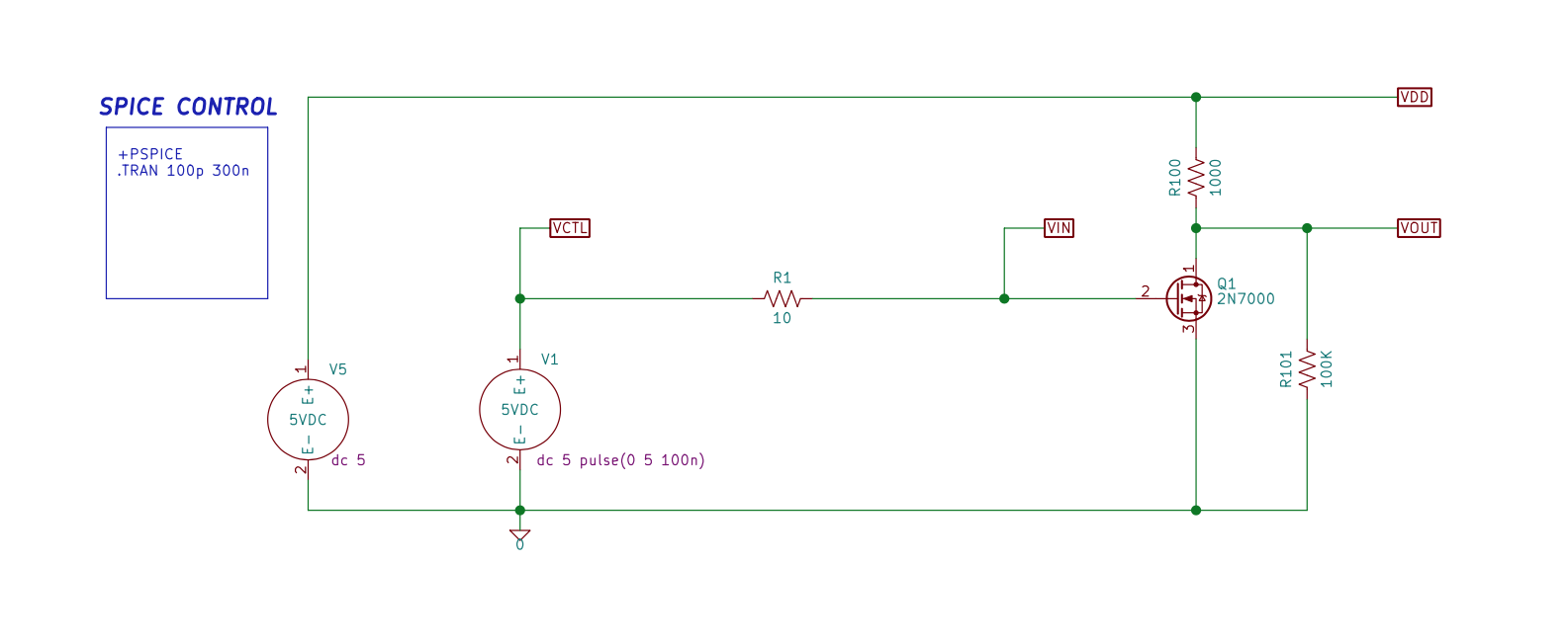
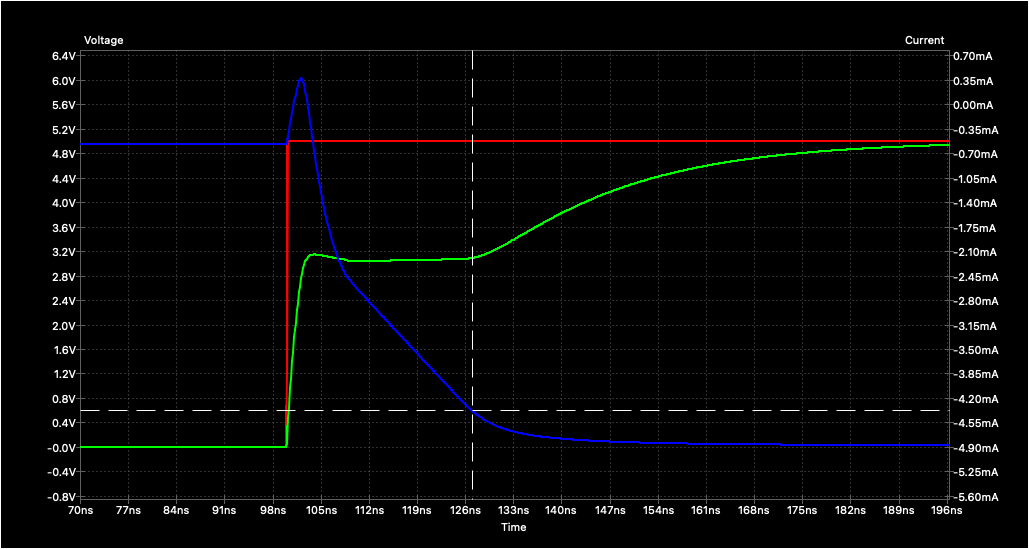
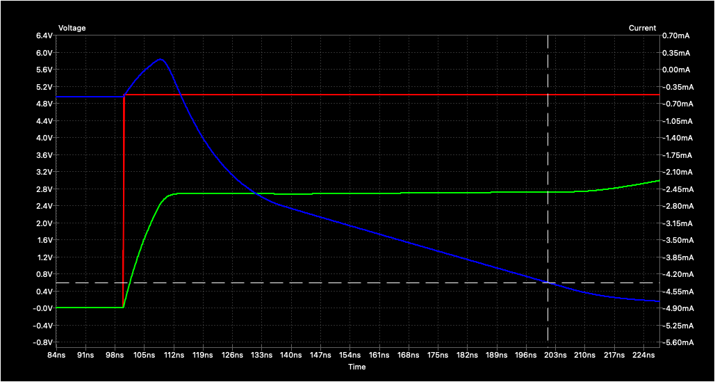
This is a simple circuit to test the impact of trace resistance, R1, on rise time (or more strictly speaking, fall time since this is an inverting circuit). The voltage source V5 provides load voltage, and V1 provides the gate drive signal pulse which happens at 100 ns. VOUT is the inverted output signal, and we observe the time it takes from pulsing the gate until VOUT drops to below an arbitrary 0.6 volts.
Before showing the results, I’d like to point out one feature that’s made possible by the close integration of SPICE simulation within a schematic capture tool. In the case of KiCad / ngspice, once you’ve loaded and run a simulation, you can easily observe the simulation results as you change, or tune, a particular component’s value. You click the TUNING button, go into the schematic and click on the component of interest. A tuning slider pops up as seen below. Then, in real time, you can tweak the value (of R1 in this case) and see how it impacts the simulation.
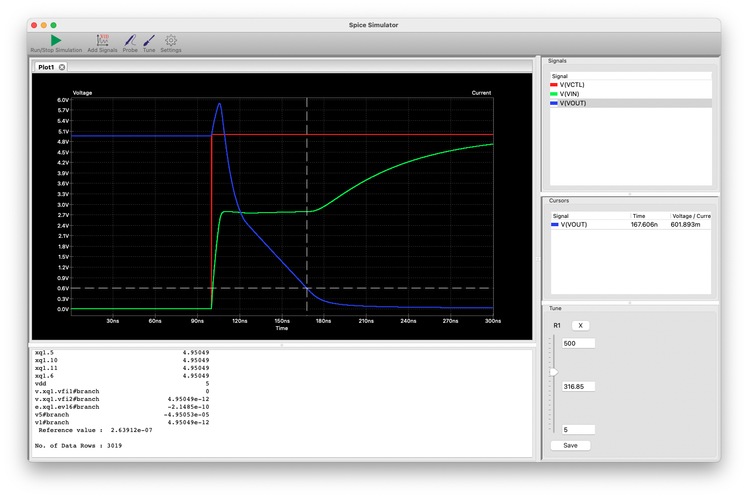
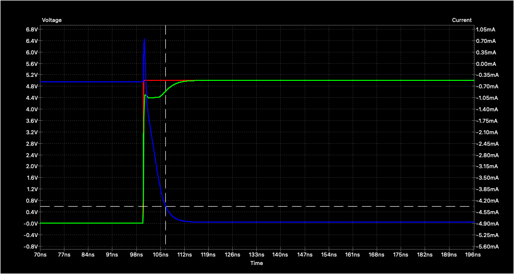
I took a snapshot of VOUT at three different values of R1 and noted the transition output times in each case using the measurement cursors of the simulator. I also note the theoretical maximum frequency of a square wave signal through such a circuit (taking the reciprocal of double the rise time).
- 5 ohms ~ 6 ns ~ 83.3 MHz
- 100 ohms ~ 27 ns ~ 18.5 MHz
- 500 ohms ~ 100 ns ~ 5.0 MHz
You can see the waveforms in the graphs below:
If you would like to play around with this SPICE simulation, check out this GitHub repository that I prepared for this project’s KiCad simulation files, and any other simulations we might generate as this series progresses.
Fun Facts
In this write-up about dynamic signals, I thought I would mention the terminology for the complex values of resistance and conductance. If you’re an electrical engineer, these might look familiar. Otherwise, replace the j with an i and it might jog your memory:
Z = R + jX (all quantities in ohms) Impedance = Resistance + Reactance Y = G + jB (all quantities in mhos) Admittance = Conductance + Susceptance Wrap up
It is expected that increasing the trace resistance will increase the response time (rise or fall). But the numbers obtained by this simulation seem manageable, and I’m not terribly concerned at this point. Just like we must take care when driving higher current signals like relays or LEDs when using conductive ink traces, we need to be aware of trace resistance when using high speed signals. I’ll also point out that sometimes we want to slow down the rise times of high speed signals — for example, to reduce unintentional electromagnetic radiation.
Next article I’ll introduce the demonstration circuit board that will be making in order to measure some of these effects, and see first hand the ramifications of using less-than-ideal circuit board traces.
Part 4: Making a reference PCB continues here
Notes
The simulation files can be found at this GitHub repository
- Typical TTL Input Circuit Diagram Fig 2.2 and 2.3, pg 2-9, 1978 Fairchild TTL Data Book https://archive.org/details/bitsavers_fairchilddldTTLDataBook_39509923
Addeddate 2013-08-12 17:19:03
Bitsavers-filename /pdf/fairchild/_dataBooks/1978_Fairchild_TTL_Data_Book.pdf
Coverleaf 0
Identifier bitsavers_fairchilddldTTLDataBook_39509923
Identifier-ark ark:/13960/t44q9pd9s
Ocr ABBYY FineReader 8.0
Ppi 600