In this article, I'll discuss the testing approach for this project. Since I'm basically lazy, the goal is to keep things as simple as possible and try not to reinvent the wheel.
Testing Approach
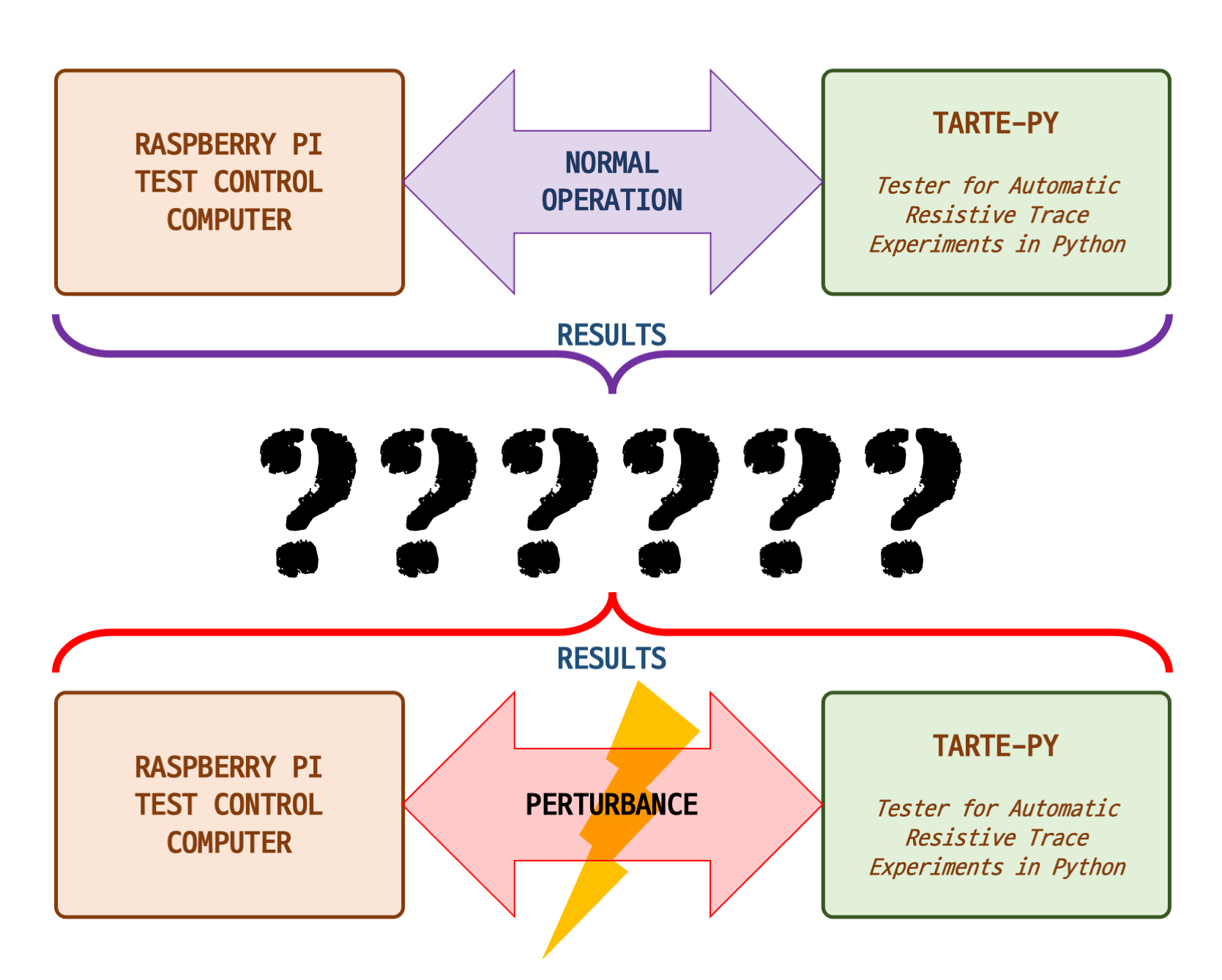
The gist of these tests is to take various parts of the circuit of interest, say a serial data link, and first observe it while its operating in the normal way. In this project, normal means with highly conductive copper traces. In the serial data example, this would mean checking the that data is not corrupted and perhaps watching the waveform on the oscilloscope.
Then next we will perturb the circuit by increasing the trace resistance while observing the circuit's performance. Afterwards, the plan is to come up with guidelines for implementing each type of circuit when using conductive inks.
Test Bench Setup
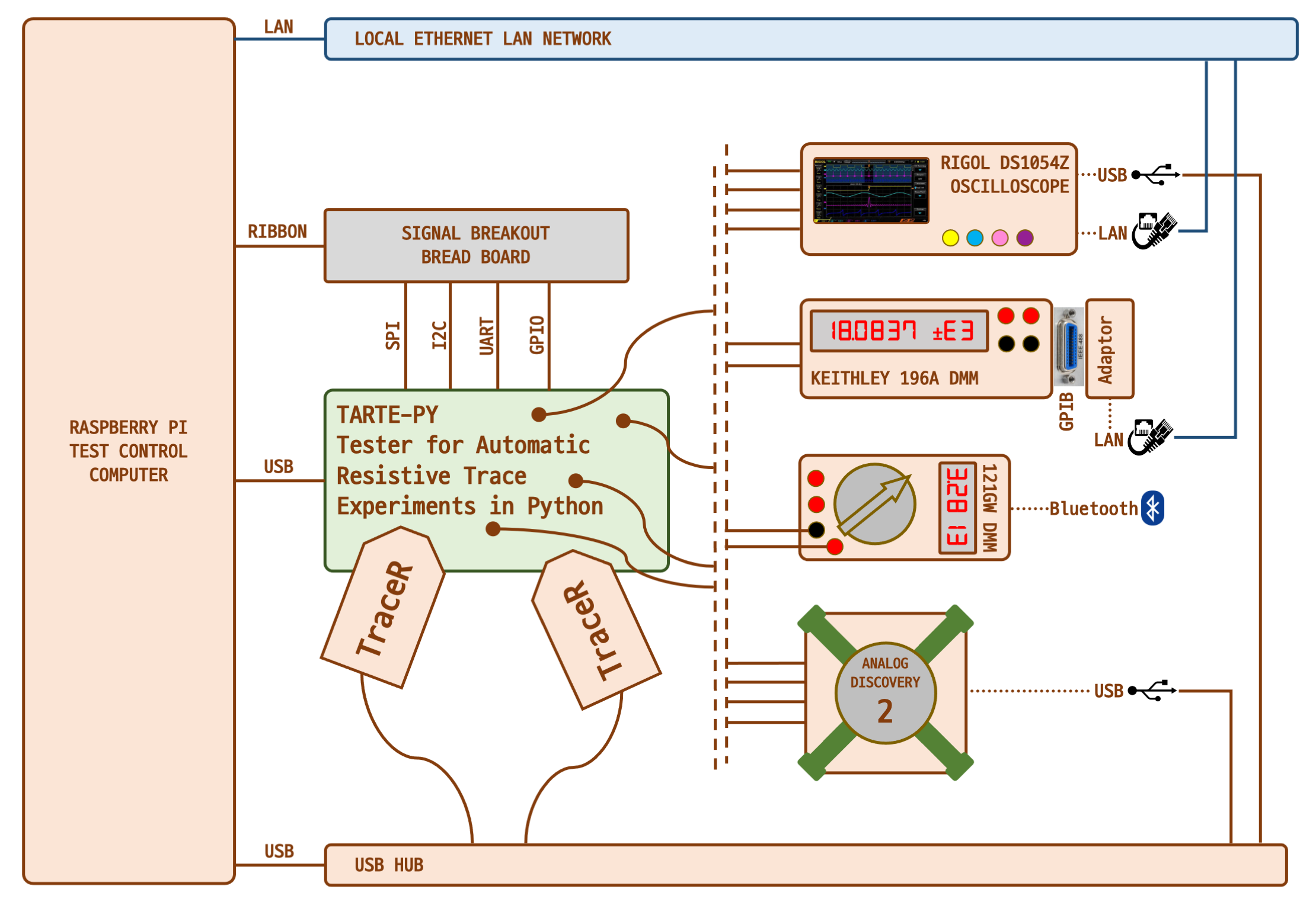
The block diagram below expands on the one introduced in Part 2. I've updated it to include the various instruments and interfaces that I plan to use. Notice that the demonstration MCU board now has a name, Tarte-Py which will be discussed in the next article.
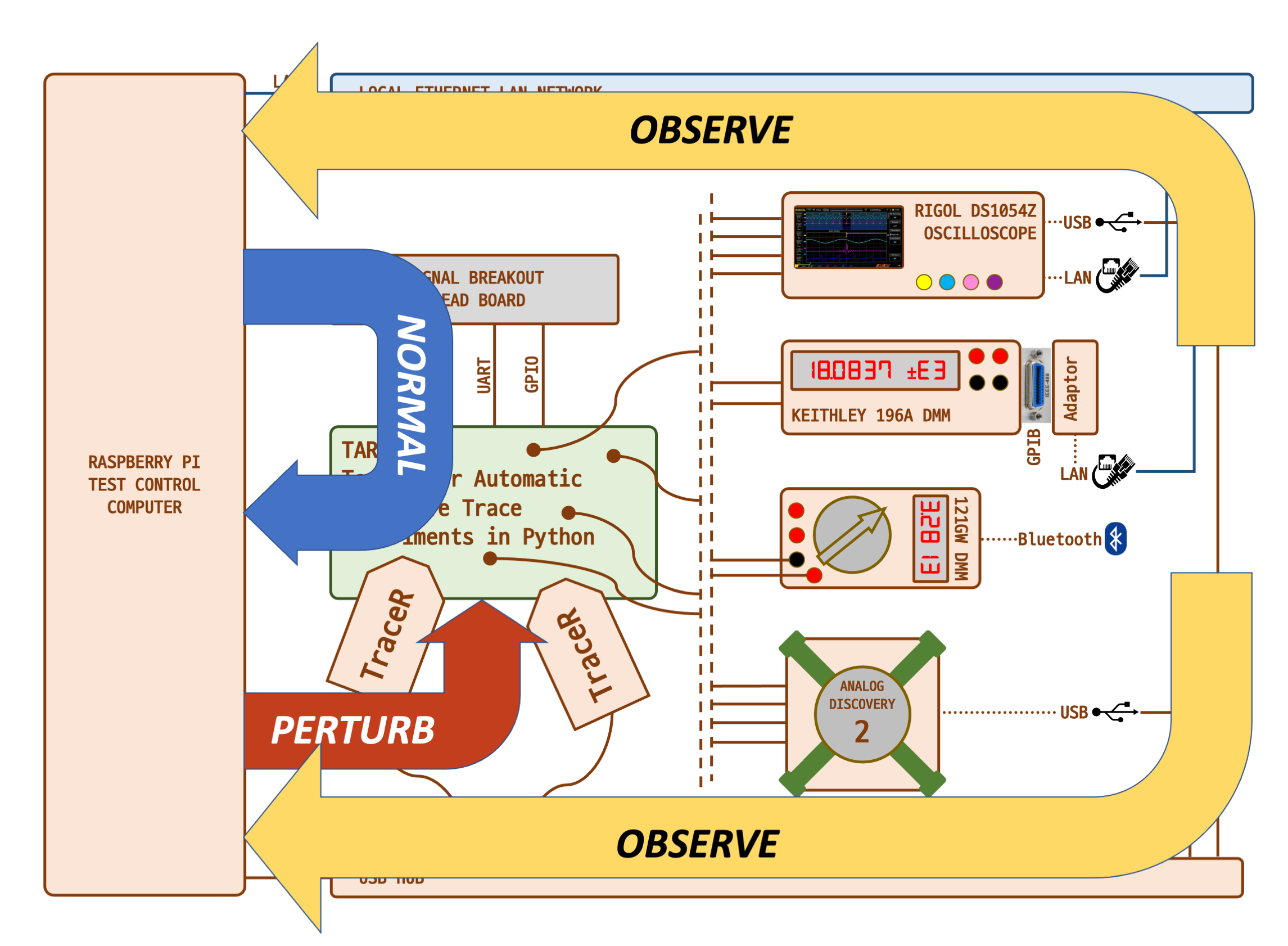
This next diagram combines the testing concept with the actual test bench setup.
Test Control Computer
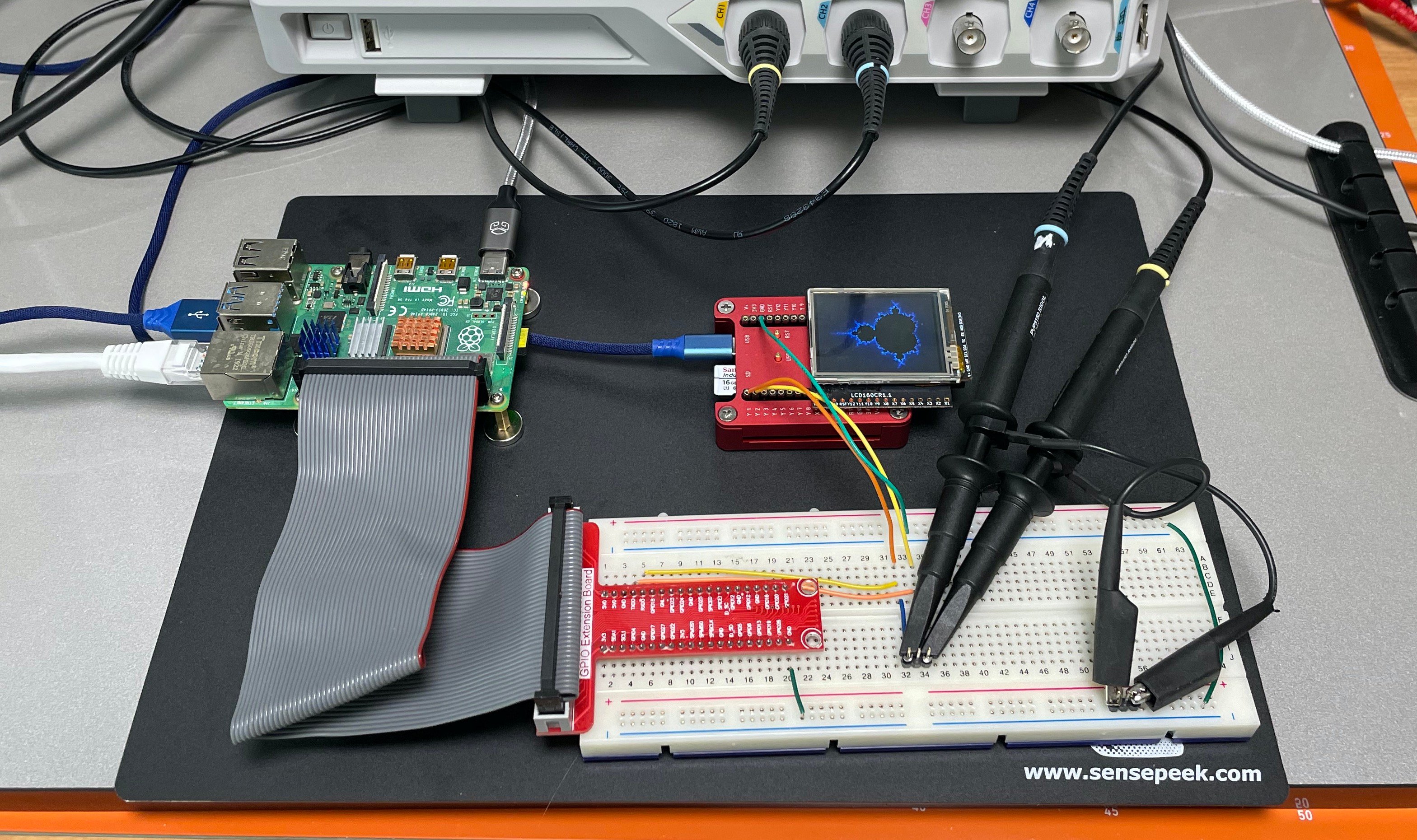
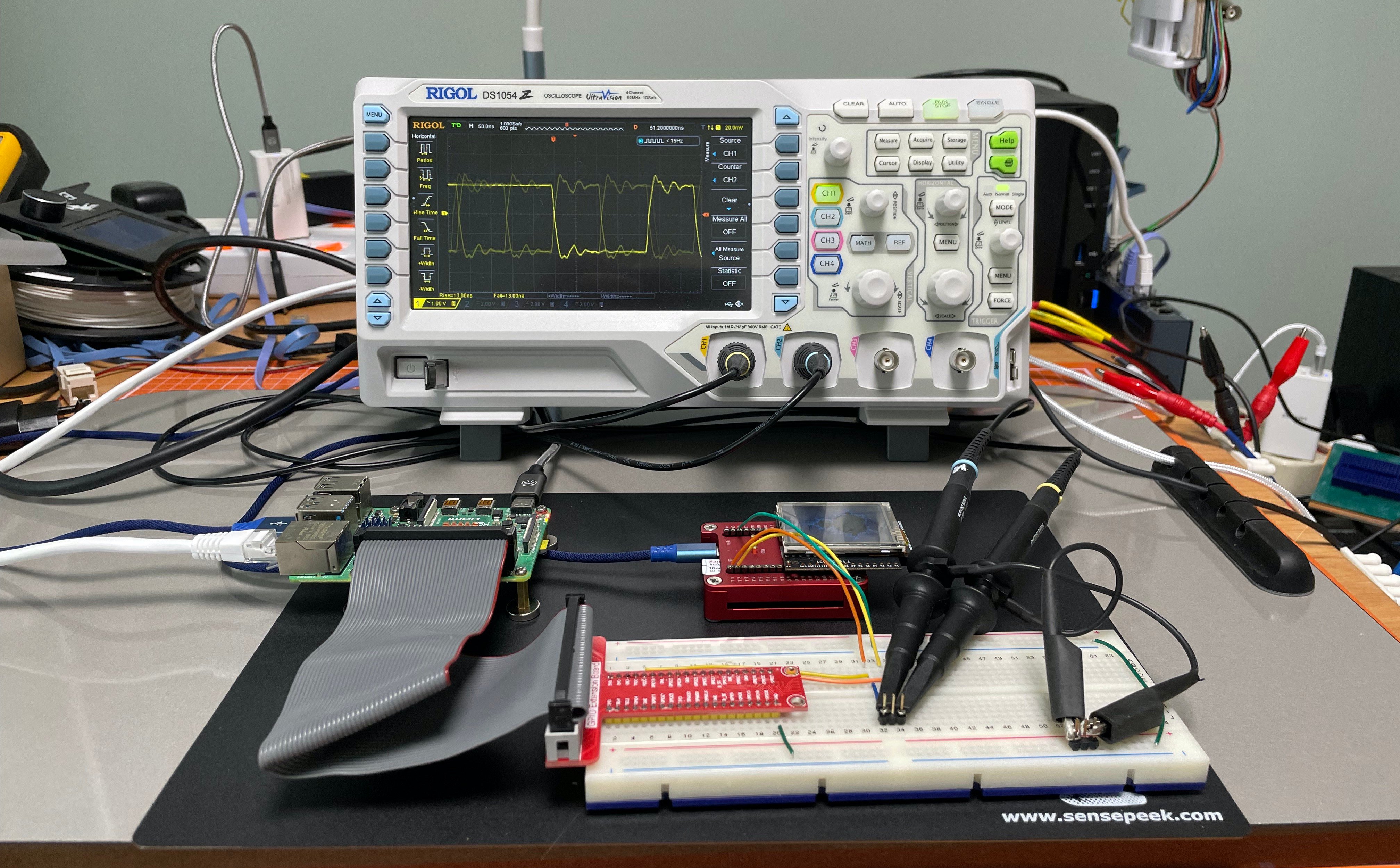
As mentioned previously, the main test control computer will be a Raspberry Pi. I'm specifically using a Pi 4 Model B Rev 1.1, but almost any modern version should work. In the photo below, the Pi is on the top left and connected to a signal break-out breadboard at the bottom. In this picture, I've connected up the serial ports of the Raspberry Pi and a Micropython Pyboard (used as a Tarte-Py stand-in until those boards are ready), and connected an oscilloscope to see the signals.
Demonstration Microcontroller: Tarte-Py
The microcontroller board is the center for all these test, under the control of the test computer. I already outlined this board in Part 4, and I will review its design in the next article.
Trace Resistance Simulators: TraceR
The TraceR modules were described in the last article. They will be used to perturb the circuit by simulating increased trace resistances. So what else is needed? Nothing remarkable, just a few common pieces of test gear that can found in most electronics labs these days.
Rigol DS1054Z, Four-channel Digital Oscilloscope
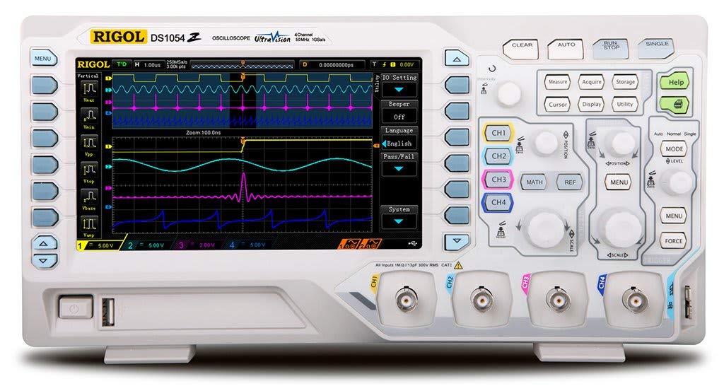
A common workhorse in labs, this model was introduced in 2014 and even today still packs a lot of features for a reasonable price. It has USB and Ethernet networking support, as well as a USB thumb drive interface to store screen captures, data, and scope settings. Many models also have protocol decoders which lets you view common serial data streams in an appropriate format.
Keithley 195A, Benchtop 5-1/2 Digit Digital Multimeter
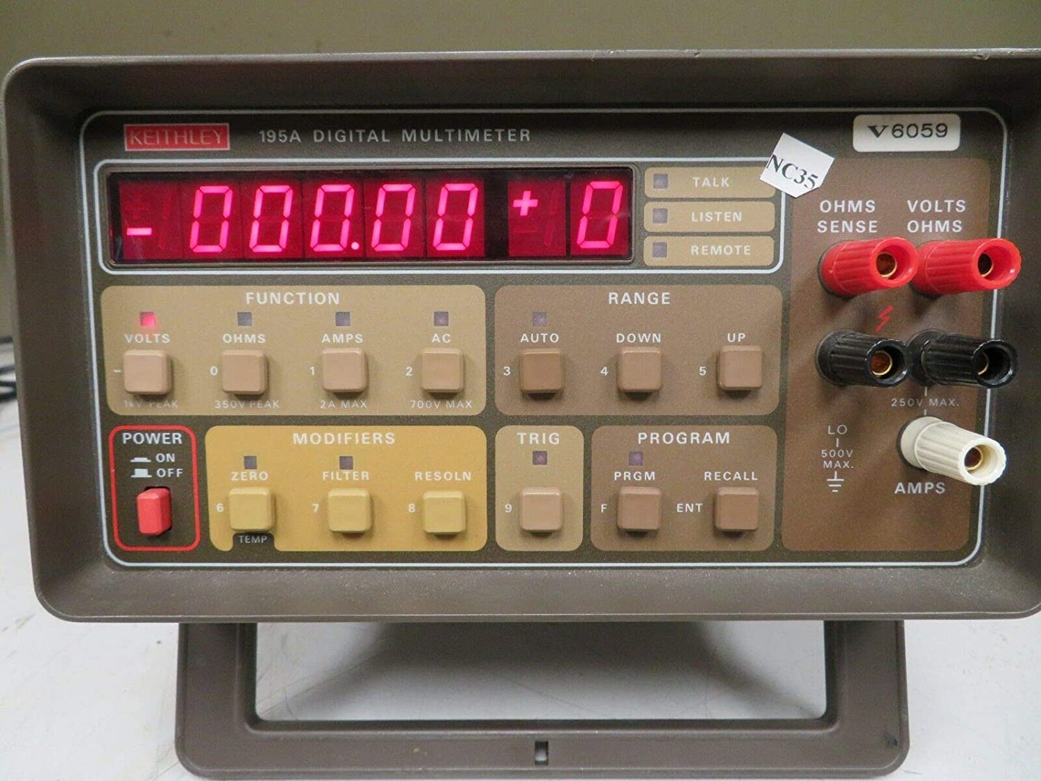
This is an old meter from the 1980s, but I am including it not only because I have one, but because it demonstrates an often overlooked point for hobbyists and small engineering labs on a tight budget. These can be obtained at a good price on the used market, can still be calibrated to traceable standards, and can be interfaced with your modern equipment without a lot of effort. Keithley Instruments is now part of Tektronix.
EEVBlog/UEI 121GW 4-3/4 Handheld Digital Multimeter
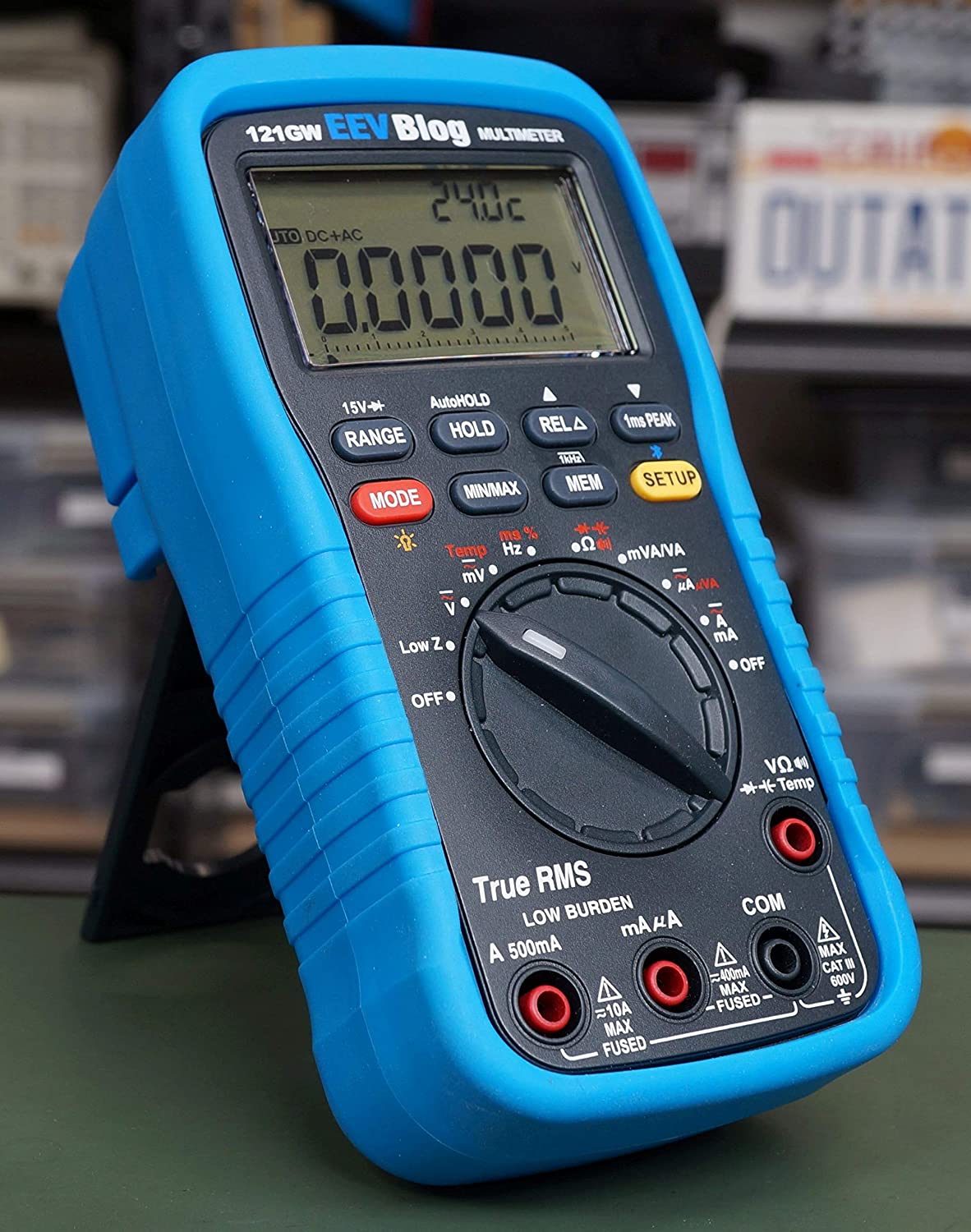
This is the Swiss army knife of multimeters, designed by an electronics engineer for electronic engineers. I will be using it on this project as a secondary DMM to the Keithley when needed. It's also convenient because it has a Bluetooth interface and SD card logging.
Analog Discovery 2, Multifunction Mixed Signal Analyzer
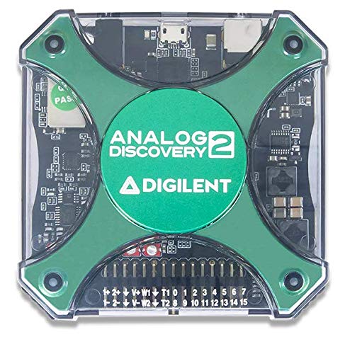
This is an interesting device which melds an oscilloscope, logic analyzer, signal / pattern generator, discrete I/O, power supply, etc., into something the size of a ham sandwich. Developed jointly by Analog Devices and Digilent almost ten years ago, this unit let students could carry an entire laboratory in their backpack for the cost of a typical textbook. Digilent is now owned by National Instruments.
Writing test software in Python
If you are fortunate enough to work in a lab equipped with high-end test equipment, the issue of communicating with test gear could be minor. These setups are often networked with a package like National Instruments LabVIEW, which lets the user easily "program" a test by connecting equipment virtually with an on-screen GUI. LabVIEW which has been around since 1983 and supports a large number of devices out of the box. If you have a lot of old equipment having GPIB interfaces, then you could write a complete test program in BASIC on your old HP-85 computer (like Curious Marc does in this quick 90 second video).
For many of us in the middle, with a hodgepodge of equipment having different interfaces, there are solutions to make the task easier. I mentioned before that I will use Python to program the tester, and one reason for that choice is that one can find Python modules to communicate with many many pieces of test equipment. Many of these are supported by the user community, many by the manufacturer, but they abound. The industry's Virtual Instrument Software Architecture (VISA) standard makes much of this possible, plus a number of Python libraries like PyVISA and PyMeasure, for example.
Another suite of tools to keep in mind is the open-source sigrok project. Sigrok provides drivers, control software, and GUI tools for a wide variety of test equipment and interfaces. I am not sure whether I'll be using sigrok for these tests or not, but it's in the toolbox if needed.
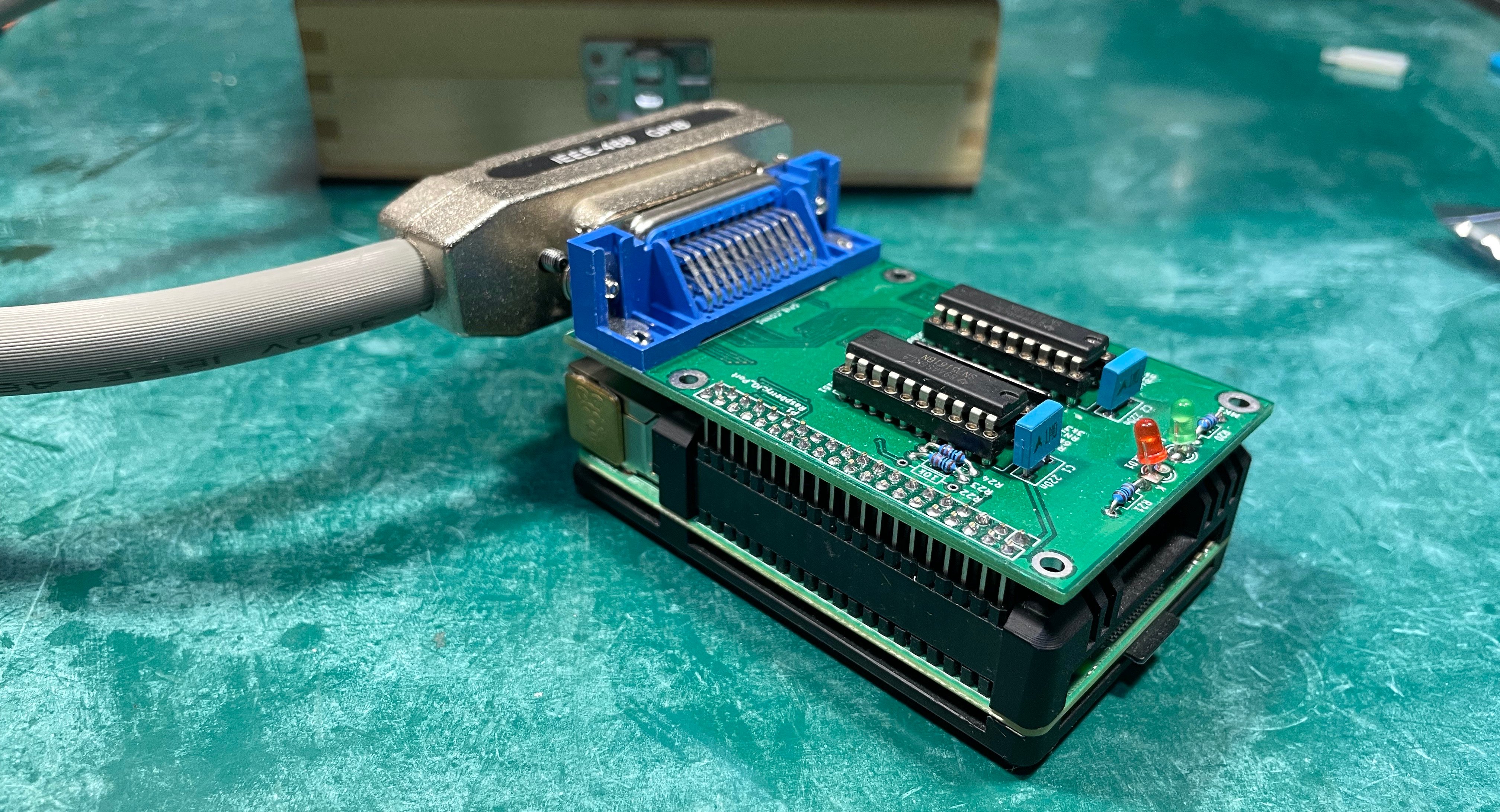
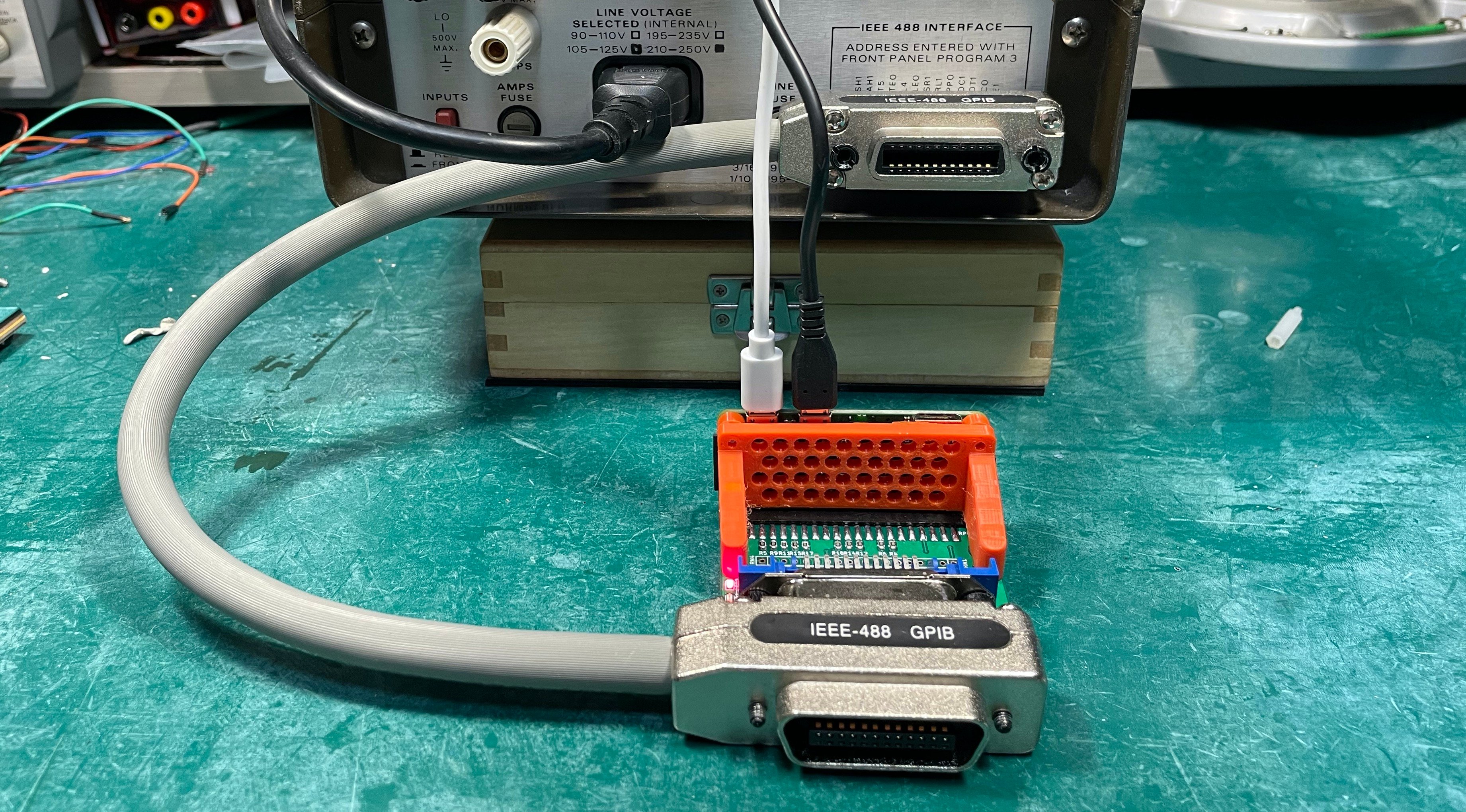
For communicating with the GPIB-equipped Keithley multimeter, I will be using the Raspberry Pi GPIB Shield open source project developed by Thomas Klima back in 2016. There are two flavors of this project: one for an ordinary Raspberry Pi board, and another for a Pi Zero board. The first one is best suited to a project where you have multiple GPIB devices controlled from a single computer. The Pi-Zero-based one which I'll be using is great for a project which only has one GPIB instrument. The entire Pi Zero + GPIB Shield assembly mounts directly on the GPIB connector of the instrument. Well, that was the plan. Unfortunately, the GPIB connector on the Keithley is upside-down. I could plug the adaptor directly onto the meter, but there would be no room for the USB cables to the Pi Zero. I've solved this by using a short GPIB cable as seen below.
To summarize, I'm grossly oversimplifying the playing field here. But the bottom line is that there are a lot of options available to talk to our instruments without writing a ton of custom code from the ground up for each one.
What to Test?
When making the demonstration MCU board, I included a lot of test points where we can interrupt the circuit and raise the resistance. But after considering our back-of-the-envelope calculations earlier in this series, there are three tests I think we should focus on to begin with.
High Current Drive
Well, "high current" from the perspective of microcontroller designs, that is. This test will examine output signals in the tens of milliamps range -- for example LEDs and a relay. It won't be a very complicated test, and I expect the results will reveal some practical design and layout considerations for making these types of circuits with conductive ink traces.
Power Supply Input
Here the high current load will be our microcontroller circuit. This test should be similar to the above one, although interpreting the results might be a bit more challenging.
High Speed Communications
Finally we will look at high speed serial communications, say up to 10 or 15 MHz, and check for any signal degradation and/or data errors. To give you an idea of how this might look, I've setup a preliminary test station and sent some dummy serial data from the test computer to a real Pyboard (our custom MCU board isn't ready yet). The Pyboard just receives data and echoes it back for this simple demo today.
Here is an oscilloscope screen capture of the serial data exchange of the message hello.
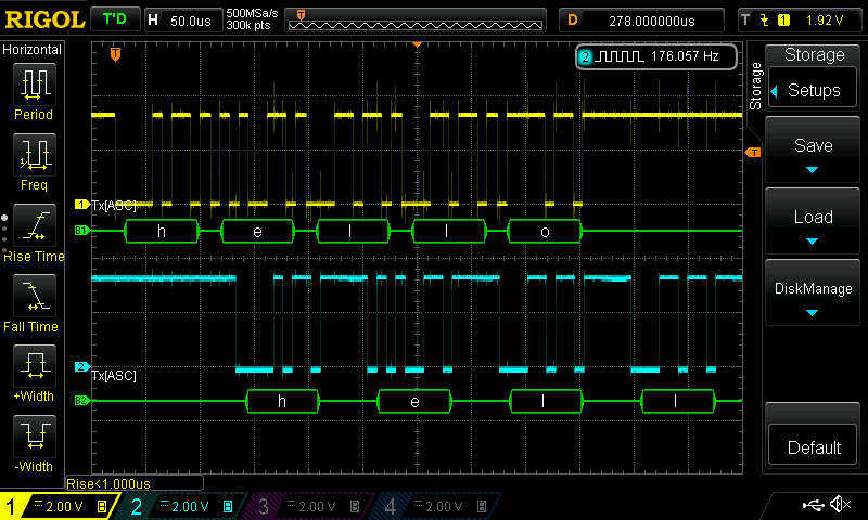
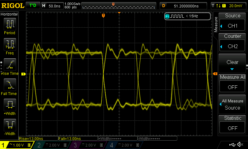
But more importantly, we will be looking for increased rise and fall times. We can set up the oscilloscope to show an eye-pattern-like display and measure the edge times. In this scope screen capture, I was operating the serial port at 10 Mbps (100 ns period), and the scope reports edge times of 13 ns.
Do you have any other tests you'd like to see? If so, let me know in the comment section below.
What's Next?
Next up I'll write in more depth about the microcontroller board which I've dubbed the Tarte-Py You'll have to wait until then to learn why. As for the hardware to actually perform these tests, here's the status. One TraceR module was built for testing. I spun an update to the PCB, and those have already arrived along with all the parts. Assembly, testing and calibration is all that remains.
PCBs and all parts for the Tarte-Py have arrived. This board is big enough that I'm going to assemble it using my own reflow oven for the first time. Wish me luck. I will document the process in the build logs in the GitHub repositories (more about those next time).
And finally, I have a lot of Python scripts to write. A few days ago, I tried to talk to the 121GW multimeter over Bluetooth. After two hours, I quit in frustration, but not after convincing myself that I could solve the problem later on when I calmed down (it has to do with Bluetooth LE drivers, and not the 121GW itself). I then tried to talk to the Rigol oscilloscope, and was pleasantly surprised to be talking to that in about minutes.
My first serious script will be to calibrate the TraceR modules. I my initial test of the prototype assembly, I just issued the resistance value in Digipot counts. Using the bench multimeter, I'll step through all Digipot counts, measure the actual resistance, and build a calibration lookup table. That way, I can tell the TraceR the desired resistance directly in ohms.
Notes
-
Rigol oscilloscope photo from Amazon https://www.amazon.com/dp/B012938e76
-
Keithley 195A photo from Amazon https://www.amazon.ca/dp/B07HPF83VX
-
121GW DMM from Amazon https://www.amazon.com/dp/B07W8C3T3J
-
Analog Discovery 2 from Amazon https://www.amazon.com/dp/B018OPOQOS